AXLE AND DIFFERENTIAL REAR DIFFERENTIAL CARRIER ASSEMBLY(for K3-VE) DISASSEMBLY
PROCEDURE

 41110
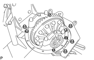
1.FIX REAR DIFFERENTIAL CARRIER ASSEMBLY
2.INSPECT RUNOUT OF REAR DRIVE PINION COMPANION FLANGE SUB-ASSEMBLY
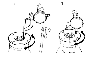
| *a | Vertical Runout |
| *b | Lateral runout |
| *c | 30 mm (1.18 in.) |
Using a dial indicator, measure the runout of the companion flange vertically and laterally.
- Maximum runout:
Runout Maximum Vertical runout 0.10 mm (0.0039 in.) Lateral runout 0.10 mm (0.0039 in.)
If the runout is greater than the maximum, replace the companion flange.
3.INSPECT RUNOUT OF DIFFERENTIAL RING GEAR
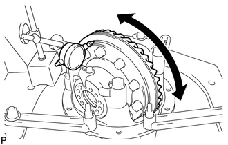
Using a dial indicator, check the runout of the ring gear.
- Maximum runout:
0.10 mm (0.0039 in.)
If the runout is greater than the maximum, replace the ring gear with a new one.
4.INSPECT DIFFERENTIAL RING GEAR BACKLASH
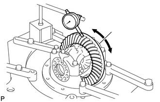
Using a dial indicator, check the backlash of the ring gear.
- Backlash:
0.08 to 0.13 mm (0.0031 to 0.0052 in.)
If the backlash is not within the specification, adjust the side bearing preload or repair as necessary.
- HINT:
-
Perform the measurements at 3 or more positions around the circumference of the ring gear.
5.INSPECT DIFFERENTIAL DRIVE PINION PRELOAD
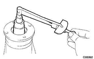
Using a torque wrench, measure the preload of backlash between the drive pinion and ring gear.
- Preload (at starting):
Bearing Standard New bearing 0.57 to 0.96 N*m (5.8 to 9.8 kgf*cm, 5.0 to 8.5 in.*lbf) Used bearing 0.49 to 0.78 N*m (5.0 to 8.0 kgf*cm, 4.5 to 7.0 in.*lbf)
If necessary, disassemble and inspect the differential.
- HINT:
-
Make a note of the values for the below total preload inspection procedure.
6.INSPECT TOTAL PRELOAD
Using a torque wrench, measure the preload with the teeth of the drive pinion and ring gear in contact.
- Total preload (at starting):
Drive pinion preload plus 0.20 to 0.39 N*m (2.0 to 4.0 kgf*cm, 1.8 to 3.5 in.*lbf)
If necessary, disassemble and inspect the differential.
7.REMOVE REAR DRIVE PINION NUT
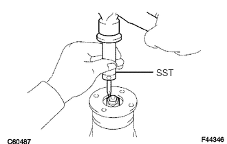
Using SST and a hammer, loosen the staked part of the nut.
- SST
- 09930-00010
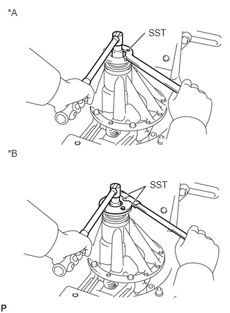
| *A | for Manual Transmission |
| *B | for Automatic Transmission |
Using SST to hold the companion flange in place, remove the nut.
for Manual Transmission:
- SST
- 09330-87301
for Automatic Transmission:
- SST
- 09330-00021
09950-30012 (09955-03030)
41204
8.REMOVE REAR DRIVE PINION COMPANION FLANGE SUB-ASSEMBLY
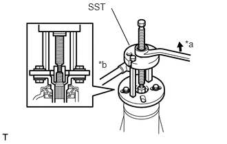
| *a | Turn |
| *b | Hold |
Using SST, remove the companion flange.
- SST
- 09950-30012 (09951-03010, 09953-03010, 09954-03010, 09955-03030, 09956-03020)
- NOTICE:
-
Before using SST (center bolt), apply hypoid gear oil to its threads and tip.
41252
9.REMOVE REAR DIFFERENTIAL DUST DEFLECTOR
- HINT:
-
Remove the dust deflector only when replacement is necessary due to damage or deformation.
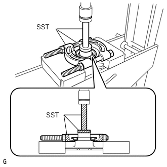
Using SST and a press, press out the dust deflector.
- SST
- 09950-60010 (09951-00430)
09950-70010 (09951-07150)
09950-00020
- NOTICE:
-
Do not drop the companion flange.
41201C
10.REMOVE REAR DIFFERENTIAL CARRIER OIL SEAL
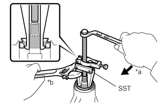
| *a | Turn |
| *b | Hold |
Using SST, remove the oil seal from the differential carrier.
- SST
- 09308-10010
41201B
11.REMOVE REAR DRIVE PINION FRONT TAPERED ROLLER BEARING
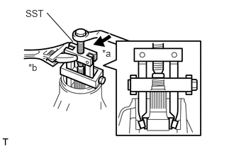
| *a | Turn |
| *b | Hold |
Using SST, remove the roller bearing (inner) from the drive pinion.
- SST
- 09556-30010
41201E
12.REMOVE REAR DIFFERENTIAL DRIVE PINION SPACER FRONT ADJUST SHIM
41231
13.REMOVE REAR DIFFERENTIAL DRIVE PINION BEARING SPACER
41316
14.REMOVE REAR DIFFERENTIAL BEARING ADJUSTING NUT LOCK
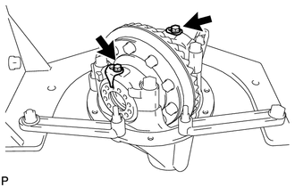
Remove the 2 bolts and 2 adjusting nut locks.
41311J
15.REMOVE REAR DIFFERENTIAL CASE
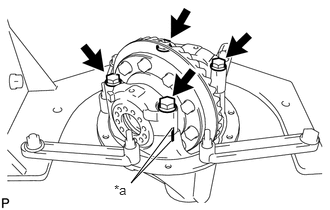
| *a | Matchmark |
Place matchmarks on the bearing cap and differential carrier.
Remove the 4 bolts and 2 differential bearing caps.
Remove the 2 adjusting nuts.
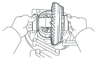
Remove the rear differential case assembly from the differential carrier.
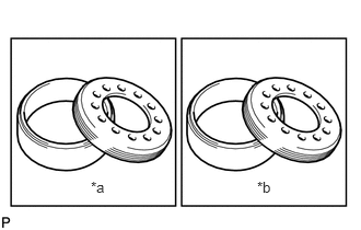
| *a | RH |
| *b | LH |
Put indication marks of the right and left (back side, tooth surface side) on the adjusting nut and case bearing (outer race), or separate them clearly.
16.REMOVE DIFFERENTIAL DRIVE PINION
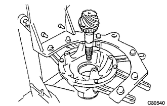
Remove the drive pinion and bearing spacer from the differential carrier.
41201A
17.REMOVE REAR DRIVE PINION REAR TAPERED ROLLER BEARING
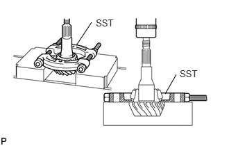
Using SST and a press, press out the roller bearing (inner) from the drive pinion.
- SST
- 09950-00020
- NOTICE:
-
Do not drop the drive pinion.
- HINT:
-
If the drive pinion or ring gear is damaged, replace them as a set.
41201B
18.REMOVE REAR DRIVE PINION FRONT TAPERED ROLLER BEARING
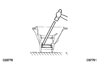
Using a brass bar and hammer, tap out the outer race from the carrier.
- HINT:
-
If the bearing or outer race is damaged during removal, replace it.
41201A
19.REMOVE REAR DRIVE PINION REAR TAPERED ROLLER BEARING
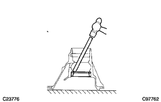
Using a brass bar and hammer, tap out the rear tapered roller bearing (outer) from the carrier.
- HINT:
-
If the bearing is damaged during removal, replace it.
41201D
20.REMOVE REAR DIFFERENTIAL DRIVE PINION PLATE WASHER
21.REMOVE DIFFERENTIAL RING GEAR
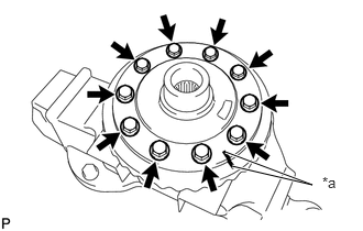
| *a | Matchmark |
Place matchmarks on the ring gear and differential case.
Remove the 10 bolts.
Using a plastic-faced hammer, tap on the ring gear to separate it from the differential case.
22.INSPECT DIFFERENTIAL CASE ASSEMBLY RUNOUT
Install the rear differential case bearing onto the differential case.
Install the differential case onto the differential carrier.
Install the 2 bearing caps onto the differential carrier with the 4 bolts.
- Torque:
- 84 N*m (852 kgf*cm, 62 ft.*lbf)
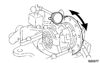
Using a dial indicator, measure the differential case runout.
- Maximum runout:
0.05 mm (0.002 in.)
Remove the differential case.
Remove the rear differential case bearing.
41301A
23.REMOVE REAR DIFFERENTIAL CASE BEARING
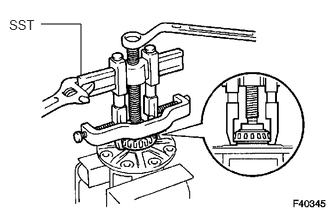
Using SST, remove the 2 bearings from the differential case.
- SST
- 09950-60010 (09951-00410)
09950-40011 (09951-04010, 09952-04010, 09953-04030, 09954-04010, 09955-04061, 09957-04010, 09958-04011)
- HINT:
-
Do not remove the case bearing unless replacing the differential case.
41311J
24.DISASSEMBLE REAR DIFFERENTIAL CASE
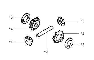
| *1 | Pinion gear |
| *2 | Pinion shaft |
| *3 | Side gear thrust washer |
| *4 | Side gear |
Remove the following parts from the differential case.