FRONT SUSPENSION FRONT LOWER SUSPENSION ARM REMOVAL
PROCEDURE

 1.REMOVE FRONT WHEEL
48069
2.REMOVE FRONT LOWER SUSPENSION ARM
Remove the clip and nut.
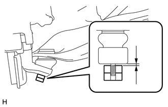
| *a | 1 mm (0.04 in.) |
Install SST to the front lower suspension arm ball joint as shown in the illustration.
- SST
- 09960-20010 (09961-02050, 09961-02050)
- NOTICE:
-
Check that the clearance measurement between SST and the steering knuckle is 1 mm (0.04 in.).
Using SST, remove the front lower suspension arm ball joint from the steering knuckle as shown in the illustration.
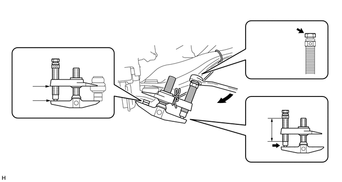
| *1 | Apply grease | *2 | Apply grease |
| *3 | Place the wrench here | *4 | Turn |
- SST
- 09960-20010 (09961-02050, 09961-02050)
- NOTICE:
-
Apply grease to the threads and end of the SST bolt.
- HINT:
- ·
Install SST so that A and B are parallel.
·Be sure to place a wrench on the part indicated in the illustration.
·Do not damage the front lower suspension arm ball joint dust cover.
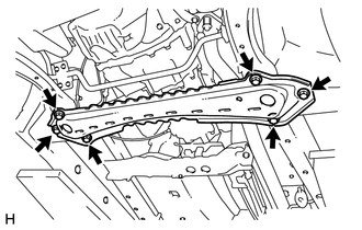
Remove the 6 bolts and remove the front lower suspension crossmember sub-assembly.
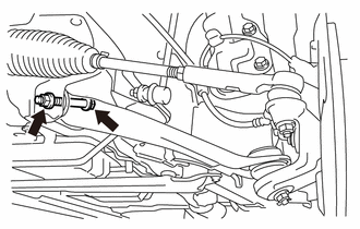
Remove the nut, bolt, 2 plate washers and front lower suspension arm.
- NOTICE:
-
Keep the bolt from rotating and turn the nut.
48069
3.INSPECT FRONT LOWER SUSPENSION ARM
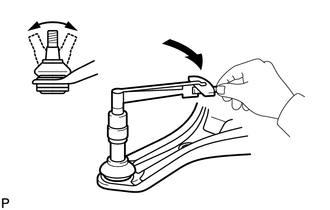
As shown in the illustration, flip the ball joint stud back and forth 5 times before installing the nut.
Using a torque wrench, turn the nut continuously at a rate of 2 to 4 seconds per turn and take the torque reading on the 5th turn.
- Turning torque:
0.8 to 4.5 N*m (8 to 46 kgf*cm, 7 to 40 in.*lbf)
Check for any cracks and grease leakage on the ball joint dust cover.