RM19Y0E
_55
Steering
_002997
POWER ASSIST SYSTEMS
_0015160
POWER STEERING SYSTEM
C
POWER ASSIST SYSTEMS POWER STEERING SYSTEM C1551/51 IG Power Supply Voltage Malfunction
DESCRIPTION
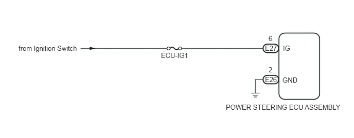
The power steering ECU assembly distinguishes the ignition switch status as ON or off through the IG power source circuit.
| DTC No. | Detection Item | DTC Detection Condition | Trouble Area | Warning Indicate | Return-to-normal Condition |
|---|---|---|---|---|---|
| C1551/51 | IG Power Supply Voltage Malfunction | Open or short in IG power source circuit with ignition switch ON. | ·
ECU-IG1 fuse ·
IG power source circuit ·
Power steering ECU |
Comes on | Ignition switch ON again |
WIRING DIAGRAM
0.375,0.896 1.615,1.104
1.24,0.208
10
from Ignition Switch
3.26,1.042 3.844,1.208
0.583,0.167
10
ECU-IG1
5.365,1.531 5.635,1.688
0.271,0.156
10
E26
5.438,1.333 5.542,1.49
0.104,0.156
10
2
5.365,0.896 5.635,1.052
0.271,0.156
10
E27
5.438,0.698 5.542,0.854
0.104,0.156
10
6
5.729,0.896 5.927,1.052
0.198,0.156
10
IG
5.719,1.542 6.156,1.698
0.438,0.156
10
GND
4.573,2.094 7.021,2.271
2.448,0.177
10
POWER STEERING ECU ASSEMBLY
PROCEDURE
1.READ VALUE USING INTELLIGENT TESTER (IG POWER SUPPLY)
a.
Connect the intelligent tester or Techstream to the DLC3.
b.
Turn the ignition switch to ON.
c.
Turn the tester or Techstream on.
d.
Enter the following menus: Chassis / EMPS / Data List.
- Chassis > EMPS > Data List
-
Tester Display IG Power Supply - 50003 317 10
e.
Select the item IG Power Supply in the Data List and read the value displayed on the intelligent tester or Techstream.
- Standard Voltage:
11 to 14 V
- Result:
Result Proceed to NG A OK B
A
2.CHECK HARNESS AND CONNECTOR (POWER STEERING ECU - ECU-IG FUSE AND BODY GROUND)
B
REPLACE POWER STEERING ECU ASSEMBLY
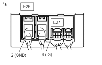
2.CHECK HARNESS AND CONNECTOR (POWER STEERING ECU - ECU-IG FUSE AND BODY GROUND)
a.
0.698,0.094 1.135,0.354
0.438,0.26
1.719,0.625 2.135,0.885
0.417,0.26
0.906,1.177 0.646,1.74
true
1.781,1.135 1.552,1.729
true
0.094,0.052 0.344,0.271
0.25,0.219
10
*a
0.375,1.771 0.979,1.979
0.604,0.208
10
2 (GND)
1.406,1.75 1.896,1.958
0.49,0.208
10
6 (IG)
0.781,0.135 1.156,0.323
0.375,0.188
10
E26
1.792,0.667 2.146,0.833
0.354,0.167
10
E27
| *a | Components with harness connected
(Power Steering ECU Assembly) |
Measure the voltage according to the value(s) in the table below.
- Standard Voltage:
Tester Connection Switch Condition Specified Condition E27-6 (IG) - Body ground Ignition switch ON 11 to 14 V
b.
Measure the resistance according to the value(s) in the table below.
- Standard Resistance:
Tester Connection Condition Specified Condition E26-2 (GND) - Body ground Always Below 1 Ω
- Result:
Proceed to OK NG
OK
REPLACE POWER STEERING ECU ASSEMBLY
NG
REPAIR OR REPLACE HARNESS OR CONNECTOR