RM19Y0E
_55
Steering
_002997
POWER ASSIST SYSTEMS
_0015160
POWER STEERING SYSTEM
J
POWER ASSIST SYSTEMS POWER STEERING SYSTEM TS and CG Terminal Circuit
DESCRIPTION
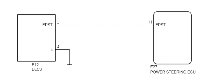
The power steering ECU can be changed from normal mode to the mode for the torque sensor zero point calibration by turning the ignition switch to ON after the DLC3 EPST and E terminals have been connected.
WIRING DIAGRAM
1.458,0.771 1.865,0.948
0.406,0.177
10
EPST
1.74,1.625 1.906,1.802
0.167,0.177
10
E
1.094,2.156 1.385,2.313
0.292,0.156
10
E12
1.094,2.313 1.479,2.469
0.385,0.156
10
DLC3
5.177,2.229 5.448,2.396
0.271,0.167
10
E27
5.177,2.406 6.813,2.563
1.635,0.156
10
POWER STEERING ECU
5.354,0.771 5.76,0.948
0.406,0.177
10
EPST
5.115,0.677 5.323,0.854
0.208,0.177
10
11
1.969,0.688 2.094,0.854
0.125,0.167
10
3
1.969,1.531 2.104,1.708
0.135,0.177
10
4
PROCEDURE
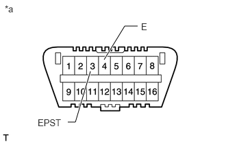
1.INSPECT DLC3 TERMINAL VOLTAGE
a.
1.031,1.854 1.146,1.854
1.146,1.854 1.375,1.083
true
2.094,0.396 1.896,0.396
1.896,0.396 1.583,0.906
true
0.073,0.052 0.24,0.219
0.167,0.167
10
*a
0.573,1.781 0.979,1.958
0.406,0.177
10
EPST
2.146,0.323 2.302,0.5
0.156,0.177
10
E
| *a | Front view of DLC3 |
Turn the ignition switch to ON.
b.
Measure the voltage according to the value(s) in the table below.
- Standard Voltage:
Tester Connection Condition Specified Condition E12-3 (EPST) - E12-4 (E) Ignition switch ON 11 to 14 V
- Result:
Result Proceed to NG A OK B
A
2.CHECK HARNESS AND CONNECTOR (DLC3 - BODY GROUND)
B
PROCEED TO NEXT SUSPECTED AREA SHOWN IN PROBLEM SYMPTOMS TABLE
2.CHECK HARNESS AND CONNECTOR (DLC3 - BODY GROUND)
a.
2.094,0.396 1.896,0.396
1.896,0.396 1.583,0.917
true
0.073,0.063 0.281,0.229
0.208,0.167
10
*a
2.146,0.323 2.333,0.479
0.188,0.156
10
E
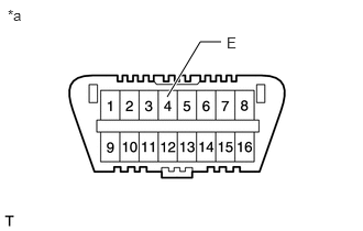
| *a | Front view of DLC3 |
Measure the resistance according to the value(s) in the table below.
- Standard Resistance:
Tester Connection Condition Specified Condition E12-4 (E) - Body ground Always Below 1 Ω
- Result:
Proceed to OK NG
OK
3.CHECK HARNESS AND CONNECTOR (POWER STEERING ECU - DLC3)
NG
REPAIR OR REPLACE HARNESS OR CONNECTOR
3.CHECK HARNESS AND CONNECTOR (POWER STEERING ECU - DLC3)
a.
Disconnect the E27 power steering ECU connector.
b.
Measure the resistance according to the value(s) in the table below.
- Standard Resistance (Check for Open):
Tester Connection Condition Specified Condition E27-11 (EPST) - E12-3 (EPST) Always Below 1 Ω
- Standard Resistance (Check for Short):
Tester Connection Condition Specified Condition E27-11 (EPST) - Body ground Always 10 kΩ or higher
- Result:
Proceed to OK NG
OK
NG
REPAIR OR REPLACE HARNESS OR CONNECTOR