RM19Y0E
_56
Audio / Visual / Telematics
_003001
PARK ASSIST / MONITORING
_0015174
TOYOTA PARKING ASSIST-SENSOR SYSTEM
J
PARK ASSIST / MONITORING TOYOTA PARKING ASSIST-SENSOR SYSTEM Indicator Circuit
DESCRIPTION
The warning indicator lights are installed in the combination meter assembly.
WIRING DIAGRAM
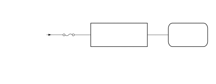
0.135,1.052 1.688,2.156
1.552,1.104
10
from Ignition or starter switch assembly
2.031,1.24 2.896,1.781
0.865,0.542
10
ECU-IG2
2.813,0.979 3.333,1.344
0.521,0.365
10
39
4.938,0.979 5.375,1.365
0.438,0.385
10
32
5.396,0.969 5.823,1.385
0.427,0.417
10
11
3.063,1.073 3.573,1.427
0.51,0.354
10
IG
4.677,1.083 5.26,1.594
0.583,0.51
10
LD
5.635,1.073 6.104,1.427
0.469,0.354
10
LD
3,1.76 4.969,2.74
1.969,0.979
10
COMBINATION METER ASSEMBLY
3.01,1.583 3.531,2.021
0.521,0.438
10
E34
5.552,1.76 7.135,2.76
1.583,1
10
CLEARANCE WARNING ECU ASSEMBLY
5.563,1.594 6.063,1.906
0.5,0.313
10
J11
CAUTION / NOTICE / HINT
- NOTICE:
-
Inspect the fuses for circuits related to this system before performing the following procedure.
PROCEDURE
1.CHECK HARNESS AND CONNECTOR (POWER SOURCE - COMBINATION METER ASSEMBLY)
a.
Disconnect the E34 combination meter assembly connector.
b.
Measure the voltage according to the value(s) in the table below.
- Standard Voltage:
Tester Connection Condition Specified Condition E34-39 (IG) - Body ground Ignition switch ON 11 to 14 V
- Result:
Proceed to OK NG
OK
2.CHECK HARNESS AND CONNECTOR (COMBINATION METER ASSEMBLY - CLEARANCE WARNING ECU)
NG
REPAIR OR REPLACE HARNESS OR CONNECTOR
2.CHECK HARNESS AND CONNECTOR (COMBINATION METER ASSEMBLY - CLEARANCE WARNING ECU)
a.
Disconnect the J11 clearance warning ECU assembly connector.
b.
Measure the resistance according to the value(s) in the table below.
- Standard Resistance (Check for Open):
Tester Connection Condition Specified Condition E34-32 (LD) - J11-11 (LD) Always Below 1 Ω
- Standard Resistance (Check for Short):
Tester Connection Condition Specified Condition E34-32 (LD) - Body ground Always 10 kΩ or higher
- Result:
Proceed to OK NG
OK
PROCEED TO NEXT SUSPECTED AREA SHOWN IN PROBLEM SYMPTOMS TABLE
NG
REPAIR OR REPLACE HARNESS OR CONNECTOR