THEFT DETERRENT / KEYLESS ENTRY ENGINE IMMOBILISER SYSTEM TERMINALS OF ECU
CHECK TRANSPONDER KEY COIL
Measure the voltage and check for pulses according to the value(s) in the table below.

| Terminal No. (Symbol) | Input/Output | Wiring Color | Terminal Description | Condition | Specified Condition | Related Data List Item/DTC |
|---|---|---|---|---|---|---|
| E56-1 (COL+) - E56-7 (COL-) | Input/Output | L-G - V | Key code communication | No key in ignition key cylinder | Below 1 V | - |
| Key inserted in ignition key cylinder | Pulse generation |
CHECK TRANSPONDER KEY ECU ASSEMBLY
Disconnect the E58 transponder key ECU assembly connector.
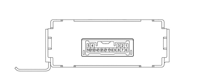
Measure the resistance and voltage according to the value(s) in the table below.
| Terminal No. (Symbol) | Input/Output | Wiring Color | Terminal Description | Condition | Specified Condition | Related Data List Item/DTC |
|---|---|---|---|---|---|---|
| E58-1 (+B) - E58-14 (E) | Input | B-W - BR | Battery | Always | 11 to 14 V | +B |
| E58-2 (IG) - E58-14 (E) | Input | R-L - BR | Ignition switch | Ignition switch off | Below 1 V | IG SW |
| Ignition switch ON | 11 to 14 V | |||||
| E58-4 (KSW) - Body ground | Input | R-W - Body ground | Unlock warning switch | No key in ignition key cylinder | Below 1 V | Key SW / B2780/15 |
| Key inserted in ignition key cylinder | 11 to 14 V | |||||
| E58-14 (E) - Body ground | - | BR - Body ground | Ground | Always | Below 1 Ω | - |
If the result is not as specified, there may be a malfunction on the wire harness side.
Reconnect the C23 transponder key ECU assembly connector.
Measure the voltage and check for pulses according to the value(s) in the table below.
| Terminal No. (Symbol) | Input/Output | Wiring Color | Terminal Description | Condition | Specified Condition | Related Data List Item/DTC |
|---|---|---|---|---|---|---|
| E58-5 (COL+) - E58-16 (COL-) | Input/Output | LG - V | Key code communication | No key in ignition key cylinder | Below 1 V | - |
| Key inserted in ignition key cylinder | Pulse generation | |||||
| E58-9 (SIO2) - E58-14 (E) | Input/Output | LG-B - BR | Immobiliser communication | Ignition switch off | Below 1 V | - |
| Ignition switch ON | Pulse generation | |||||
| E58-10 (SIO) - E58-14 (E) | Input/Output | L-R - BR | Diagnosis tester communication | Always | Pulse generation | - |
| E58-12 (IND) - E58-14 (E) | Output | L-W - BR | Security indicator light signal | Immobiliser unset | Below 1 V | - |
| Immobiliser set | Pulse generation |
If the result is not as specified, the ECU may have a malfunction.
CHECK ECM
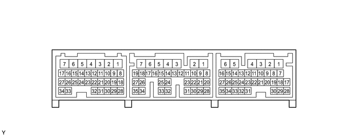
Measure the resistance and voltage, and check for pulses according to the value(s) in the table below.
| Terminal No. (Symbol) | Input/Output | Wiring Color | Terminal Description | Condition | Specified Condition | Related Data List Item/DTC |
|---|---|---|---|---|---|---|
| C23-7 (+B1) - C24-32 (E1) | Input | L - W-B | Power source of ECM | Ignition switch ON | 11 to 14 V | - |
| C24-32 (E1) - Body ground | - | W-B - Body ground | Ground | Always | Below 1 Ω | - |
| E3-7 (BAT) - C24-32 (E1) | Input | B - W-B | Battery (for measuring battery voltage and for ECM memory) | Always | 11 to 14 V | - |
| E3-32 (SIO2) - C24-32 (E1) | Input/Output | P-B - W-B | Transponder key ECU communication | Ignition switch ON | Pulse generation | - |
If the result is not as specified, the ECM may have a malfunction.