RM19Y0E
_58
Vehicle Interior
_003006
THEFT DETERRENT / KEYLESS ENTRY
_0015195
THEFT DETERRENT SYSTEM
J
THEFT DETERRENT / KEYLESS ENTRY THEFT DETERRENT SYSTEM Horn Circuit
DESCRIPTION
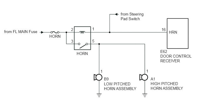
When the theft deterrent system is changed from the armed state to the alarm sounding state, the door control receiver turns on the HORN relay so that the horns can sound. The horns sound at a cycle of 0.5 seconds.
WIRING DIAGRAM
1.75,1.208 2.5,1.635
0.75,0.427
10
HORN
2.719,1.823 3.438,2.177
0.719,0.354
10
HORN
0.146,1.042 1.76,1.552
1.615,0.51
10
from FL MAIN Fuse
4.281,0.417 5.219,1.208
0.938,0.792
10
from Steering Pad Switch
5.688,1.75 6.135,2.125
0.448,0.375
10
E62
5.688,1.917 6.917,2.698
1.229,0.781
10
DOOR CONTROL RECEIVER
3.688,2.729 4.219,3.031
0.531,0.302
10
B9
3.688,2.906 5.031,3.75
1.344,0.844
10
LOW PITCHED HORN ASSEMBLY
5.344,2.729 5.802,3.063
0.458,0.333
10
A1
5.344,2.896 6.615,3.771
1.271,0.875
10
HIGH PITCHED HORN ASSEMBLY
5.99,1.063 6.625,1.51
0.635,0.448
10
HRN
5.729,0.969 6.146,1.385
0.417,0.417
10
16
2.521,1.385 2.823,1.781
0.302,0.396
10
3
3.271,1.375 3.771,1.781
0.5,0.406
10
5
2.521,0.969 2.927,1.469
0.406,0.5
10
2
3.271,0.948 3.583,1.219
0.313,0.271
10
1
5.188,2.448 5.458,2.802
0.271,0.354
10
1
3.563,2.458 3.99,2.813
0.427,0.354
10
1
CAUTION / NOTICE / HINT
- NOTICE:
-
Inspect the fuses for circuits related to this system before performing the following procedure.
PROCEDURE
1.INSPECT HORN SYSTEM
a.
Press the steering pad switch and check if the horns sound.
- Result:
Result Proceed to Horns sound A Horns do not sound B
A
2.CHECK HARNESS AND CONNECTOR (HORN RELAY - DOOR CONTROL RECEIVER)
B
2.CHECK HARNESS AND CONNECTOR (HORN RELAY - DOOR CONTROL RECEIVER)
a.
Remove the HORN relay.
b.
Disconnect the E62 door control receiver connector.
c.
Measure the resistance according to the value(s) in the table below.
- Standard Resistance (Check for Open):
Tester Connection Condition Specified Condition Relay terminal 1 - E62-16 (HRN) Always Below 1 Ω
- Standard Resistance (Check for Short):
Tester Connection Condition Specified Condition E62-16 (HRN) - Body ground Always 10 kΩ or higher
- Result:
Proceed to OK NG
OK
NG
REPAIR OR REPLACE HARNESS OR CONNECTOR