RM19Y0E
_58
Vehicle Interior
_003006
THEFT DETERRENT / KEYLESS ENTRY
_0015195
THEFT DETERRENT SYSTEM
J
THEFT DETERRENT / KEYLESS ENTRY THEFT DETERRENT SYSTEM Security Indicator Light Circuit
DESCRIPTION
When the theft deterrent system has been set, the security indicator turns on for 0.2 seconds and off for 1.8 seconds repeatedly. In this way, the security indicator blinks. Once the alarm has been set off (the theft deterrent system has entered the alarm sounding state), the security indicator stops blinking and remains ON.
- Reference:
State of Theft Deterrent System Security Indicator Condition Disarmed state OFF Armed state Blinking Alarm sounding state ON
WIRING DIAGRAM
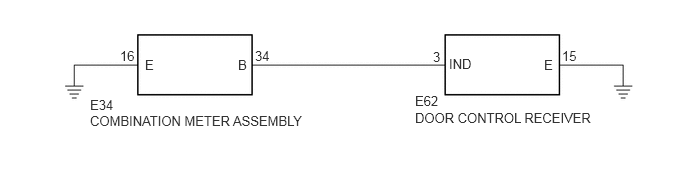
4.323,1.146 6.438,1.667
2.115,0.521
10
DOOR CONTROL RECEIVER
4.323,0.969 4.781,1.26
0.458,0.292
10
E62
0.938,1.177 3.802,1.708
2.865,0.531
10
COMBINATION METER ASSEMBLY
0.938,1.01 1.625,1.417
0.688,0.406
10
E34
2.479,0.594 2.781,0.958
0.302,0.365
10
B
1.51,0.594 1.813,0.948
0.302,0.354
10
E
4.51,0.51 4.792,0.854
0.281,0.344
10
3
2.656,0.5 3.073,0.802
0.417,0.302
10
34
1.25,0.5 1.656,0.833
0.406,0.333
10
16
4.677,0.583 5.198,0.927
0.521,0.344
10
IND
5.667,0.594 5.823,0.792
0.156,0.198
10
E
5.854,0.5 6.167,0.698
0.313,0.198
10
15
PROCEDURE
1.CHECK HARNESS AND CONNECTOR (COMBINATION METER ASSEMBLY - BODY GROUND)
a.
Disconnect the E34 combination meter assembly connector.
b.
Measure the resistance according to the value(s) in the table below.
- Standard Resistance:
Tester Connection Condition Specified Condition E34-16 (E) - Body ground Always Below 1 Ω
- Result:
Proceed to OK NG
OK
2.CHECK HARNESS AND CONNECTOR (COMBINATION METER ASSEMBLY - DOOR CONTROL RECEIVER)
NG
REPAIR OR REPLACE HARNESS OR CONNECTOR
2.CHECK HARNESS AND CONNECTOR (COMBINATION METER ASSEMBLY - DOOR CONTROL RECEIVER)
a.
Disconnect the E62 door control receiver connector.
b.
Measure the resistance according to the value(s) in the table below.
- Standard Resistance (Check for Open):
Tester Connection Condition Specified Condition E34-34 (B) - E62-3 (IND) Always Below 1 Ω
- Standard Resistance (Check for Short):
Tester Connection Condition Specified Condition E34-34 (B) - Body ground Always 10 kΩ or higher
- Result:
Proceed to OK NG
OK
3.INSPECT DOOR CONTROL RECEIVER
NG
REPAIR OR REPLACE HARNESS OR CONNECTOR
3.INSPECT DOOR CONTROL RECEIVER
a.
Reconnect the E62 door control receiver connector.
b.
Measure the voltage according to the value(s) in the table below.
- Standard voltage:
Tester Connection Condition Specified Condition E62-3 (IND) - E62-15 (E) Security indicator light illuminates during arming preparation state or alarm sounding state 11 to 14 V
- Result:
Proceed to OK NG
OK
REPLACE COMBINATION METER ASSEMBLY
NG