RM19Y0E
_58
Vehicle Interior
_003006
THEFT DETERRENT / KEYLESS ENTRY
_0015195
THEFT DETERRENT SYSTEM
J
THEFT DETERRENT / KEYLESS ENTRY THEFT DETERRENT SYSTEM Intrusion Sensor Circuit
DESCRIPTION
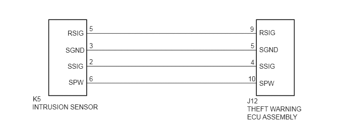
When the intrusion sensor detects any movement within the vehicle in the armed state, it sends a signal to the theft warning ECU assembly, causing the system to change to the alarm sounding state.
WIRING DIAGRAM
0.677,1.969 1.115,2.313
0.438,0.344
10
K5
0.667,2.135 2.354,2.729
1.688,0.594
10
INTRUSION SENSOR
5.104,2.01 5.563,2.281
0.458,0.271
10
J12
5.104,2.177 6.469,2.792
1.365,0.615
10
THEFT WARNING ECU ASSEMBLY
5.354,1.646 5.948,1.979
0.594,0.333
10
SPW
5.354,1.292 5.958,1.635
0.604,0.344
10
SSIG
5.354,0.948 5.979,1.25
0.625,0.302
10
SGND
5.354,0.594 6.083,1
0.729,0.406
10
RSIG
1.417,1.625 2,1.917
0.583,0.292
10
SPW
1.396,1.292 2.042,1.729
0.646,0.438
10
SSIG
1.354,0.958 2.063,1.375
0.708,0.417
10
SGND
1.396,0.604 1.969,0.99
0.573,0.385
10
RSIG
5.125,1.552 5.583,1.906
0.458,0.354
10
10
5.177,1.208 5.49,1.583
0.313,0.375
10
4
5.177,0.865 5.583,1.271
0.406,0.406
10
5
5.167,0.521 5.458,0.917
0.292,0.396
10
9
1.844,0.865 2.208,1.188
0.365,0.323
10
3
1.844,1.552 2.198,1.927
0.354,0.375
10
6
1.844,0.51 2.24,0.875
0.396,0.365
10
5
1.844,1.198 2.177,1.573
0.333,0.375
10
2
PROCEDURE
1.CHECK HARNESS AND CONNECTOR (THEFT WARNING ECU ASSEMBLY - INTRUSION SENSOR)
a.
Disconnect the K5 intrusion sensor connector.
b.
Disconnect the J12 theft warning ECU assembly.
c.
Measure the resistance according to the value(s) in the table below.
- Standard Resistance (Check for Open):
Tester Connection Condition Specified Condition K5-5 (RSIG) - J12-9 (RSIG) Always Below 1 Ω K5-3 (SGND) - J12-5 (SGND) Always Below 1 Ω K5-2 (SSIG) - J12-4 (SSIG) Always Below 1 Ω K5-6 (SPW) - J12-10 (SPW) Always Below 1 Ω
- Standard Resistance (Check for Short):
Tester Connection Condition Specified Condition K5-5 (RSIG) - Body ground Always 10 kΩ or higher K5-3 (SGND) - Body ground Always 10 kΩ or higher K5-2 (SSIG) - Body ground Always 10 kΩ or higher K5-6 (SPW) - Body ground Always 10 kΩ or higher
- Result:
Proceed to OK NG
OK
PROCEED TO NEXT INSPECTION PROCEDURE SHOWN IN PROBLEM SYMPTOMS TABLE
Click hereVehicle Interior>THEFT DETERRENT / KEYLESS ENTRY>THEFT DETERRENT SYSTEM>PROBLEM SYMPTOMS TABLE
NG
REPAIR OR REPLACE HARNESS OR CONNECTOR