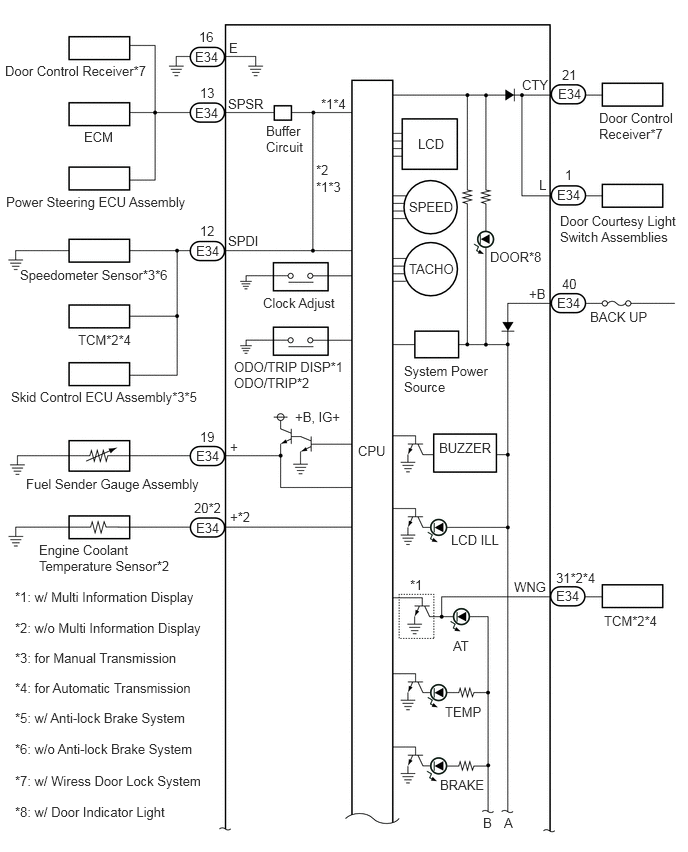
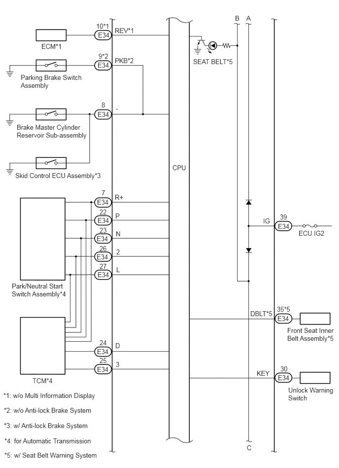
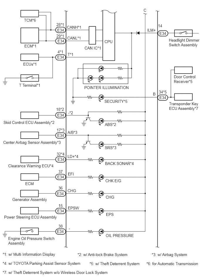
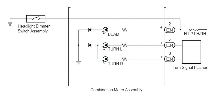
METER / GAUGE / DISPLAY METER / GAUGE SYSTEM TERMINALS OF ECU
CHECK COMBINATION METER ASSEMBLY

Measure the resistance and voltage according to the value(s) in the table below.
| Terminal No. (Symbol) | Wiring Color | Terminal Description | Condition | Specified Condition |
|---|---|---|---|---|
| E34-1 (L) - Body ground | W-L - Body ground | Door courtesy light switch signal | Ignition switch ON, courtesy light switch on | Below 0.3 V |
| Ignition switch ON, courtesy light switch off | 11 to 14 V | |||
| E34-2 (+) - Body ground | P - Body ground | Beam signal | Ignition switch ON, beam indicator light off | Below 1 V |
| Ignition switch ON, beam indicator light on | 11 to 14 V | |||
| E34-3 (+) - Body ground | G-W - Body ground | Turn signal R | Ignition switch ON, turn signal switch neutral position | Below 1 V |
| Ignition switch ON, turn signal switch turned to right | Alternating between below 1 and 11 to 14 V | |||
| E34-4 (T) - Body ground | GR - Body ground | DLC3 signal | Always | 10 kΩ or higher |
| E34-5 (+) - Body ground | L-W - Body ground | Turn signal L | Ignition switch ON, turn signal switch neutral position | Below 1 V |
| Ignition switch ON, turn signal switch turned to left | Alternating between below 1 and 11 to 14 V | |||
| E34-7 (R+) - Body ground*1 | G - Body ground | Park/neutral position switch (R) | Ignition switch ON A/T shift lever in except in R | Below 1 V |
| Ignition switch ON A/T shift lever in R | 11 to 14 V | |||
| E34-8 (-) - Body ground | B - Body ground | Brake fluid level warning light signal | Ignition switch ON, brake system warning light (red indicator) on | Below 1 V |
| Ignition switch ON, brake system warning light (red indicator) off | 11 to 14 V | |||
| E34-9 (PKB) - Body ground*2 | W-R - Body ground | Parking brake switch signal | Ignition switch ON, parking brake switch off | 11 to 14 V |
| Ignition switch ON, parking brake switch on | Below 1 V | |||
| E34-10 (REV) - Body ground | R-B - Body ground | Tachometer signal | Engine idle speed | Pulse generation
(See waveform 1) |
| E34-12 (SPDI) - Body ground | R-W - Body ground*3
L-W - Body ground*4 |
Speed signal (input) | Vehicle being driven approximately 20 km/h (12 mph) | Pulse generation
(See waveform 2) |
| E34-13 (SPSR) - Body ground | LG-R - Body ground | Speed signal (output) | Vehicle being driven approximately 20 km/h (12 mph) | Pulse generation
(See waveform 2) |
| E34-14 (ILM+) - Body ground | LG - Body ground | Illumination signal | Ignition switch ON, light control switch off | Below 1 V |
| Ignition switch ON, light control switch Tail/Head position | 11 to 14 V | |||
| E34-15 (EPSW) - Body ground | B-R - Body ground | EPS warning signal | Ignition switch ON, EPS warning light off | 11 to 14 V |
| Ignition switch ON, EPS warning light on | Below 1.7 V | |||
| E34-16 (E) - Body ground | BR - Body ground | Ground | Always | Below 1 V |
| E34-17 (A/B) - Body ground | V - Body ground | Airbag warning signal | Ignition switch ON, airbag warning light off | Below 1 V |
| Ignition switch ON, airbag warning light on | 11 to 14 V | |||
| E34-18 (-) - Body ground*5 | V-R - Body ground | ABS warning signal | Ignition switch ON, ABS warning light off | Below 1 V |
| Ignition switch ON, ABS warning light on | 11 to 14 V | |||
| E34-19 (+) - Body ground | L-Y - Body ground | Fuel sender gauge signal | Fuel F (full tank) → E (empty) | Below 1 V → 4.5 to 9 V |
| E34-20 (+) - Body ground | L - Body ground | Engine coolant temperature signal | Ignition switch ON, engine coolant temperature low | 2 to 12 V |
| Ignition switch ON, engine coolant temperature high | Below 2 V | |||
| E34-21 (CTY) - Body ground | W - Body ground | Door courtesy light switch signal | Ignition switch ON, map light assembly or No. 2 room light assembly switch DOOR, courtesy light switch on | Below 0.3 V |
| Ignition switch ON, map light assembly or No. 2 room light assembly switch DOOR, courtesy light switch off | 11 to 14 V | |||
| E34-22 (P) - Body ground*1 | P-B - Body ground | Park/neutral position switch (P) | Ignition switch ON A/T shift lever in except in P | 11 to 14 V |
| Ignition switch ON A/T shift lever in P | Below 1 V | |||
| E34-23 (N) - Body ground*1 | R-Y - Body ground | Park/neutral position switch (N) | Ignition switch ON A/T shift lever in except in N | 11 to 14 V |
| Ignition switch ON A/T shift lever in N | Below 1 V | |||
| E34-24 (D) - Body ground*1 | LG-B - Body ground | Park/neutral position switch (D) | Ignition switch ON A/T shift lever in except in D | 11 to 14 V |
| Ignition switch ON A/T shift lever in D | Below 1 V | |||
| E34-25 (3) - Body ground*1 | B-Y - Body ground | Park/neutral position switch (3) | Ignition switch ON A/T shift lever in except in 3rd | 11 to 14 V |
| Ignition switch ON A/T shift lever in 3rd | Below 1 V | |||
| E34-26 (2) - Body ground*1 | W-G - Body ground | Park/neutral position switch (2) | Ignition switch ON A/T shift lever in except in 2nd | 11 to 14 V |
| Ignition switch ON A/T shift lever in 2nd | Below 1 V | |||
| E34-27 (L) - Body ground*1 | B-L - Body ground | Park/neutral position switch (L) | Ignition switch ON A/T shift lever in except in L | 11 to 14 V |
| Ignition switch ON A/T shift lever in L | Below 1 V | |||
| E34-28 (CANH) - Body ground*6 | B - Body ground | CAN communication signal | Ignition switch ON | Pulse generation |
| E34-29 (CANL) - Body ground*6 | W - Body ground | CAN communication signal | Ignition switch ON | Pulse generation |
| E34-30 (KEY) - Body ground | L-B - Body ground | Key unlock warning signal | Key is inserted in ignition key cylinder | 11 to 14 V |
| E34-31 (WNG) - Body ground*7 | YG-B - Body ground | A/T warning light | Ignition switch ON, A/T warning light off | 11 to 14 V |
| Ignition switch ON, A/T warning light on | Below 1 V | |||
| E34-32 (LD+) - Body ground | G-Y - Body ground | Back sonar signal | Ignition switch ON, back sonar indicator light off | 11 to 14 V |
| Ignition switch ON, back sonar indicator light on | Below 1 V | |||
| E34-34 (B) - Body ground | R-G - Body ground | Security indicator light signal | Ignition switch ON, security indicator light off | Below 1 V |
| Ignition switch ON, security indicator light on | Pulse generation | |||
| E34-35 (DBLT) - Body ground | L-R - Body ground | Driver seat belt signal | Ignition switch ON, driver seat belt buckle switch on (Belt unfastened) | Below 1 V |
| Ignition switch ON, driver seat belt buckle switch off (Belt fastened) | 11 to 14 V | |||
| E34-36 (CHG) - Body ground | R-W - Body ground | CHARGE warning light | Ignition switch ON, CHARGE warning light on | Below 1.5 V |
| Ignition switch ON, CHARGE warning light off | 11 to 14 V | |||
| E34-37 (EFI) - Body ground | V-W - Body ground | MIL (check engine indicator light) signal | Ignition switch ON, MIL on | Below 1 V |
| Ignition switch ON, MIL off | 11 to 14 V | |||
| E34-38 (-) - Body ground | R - Body ground | Oil pressure warning light signal | Ignition switch ON, oil pressure warning light off | 11 to 14 V |
| Ignition switch ON, oil pressure warning light on | Below 0.75 V | |||
| E34-39 (IG) - Body ground | R-L - Body ground | Ignition switch signal | Ignition switch off | Below 1 V |
| Ignition switch ON | 11 to 14 V | |||
| E34-40 (+B) - Body ground | B-W - Body ground | Battery | Always | 11 to 14 V |
*1: for Automatic Transmission
*2: w/o Anti-lock Brake System
*3: for Manual Transmission w/ Anti-lock Brake System.
*4: except Manual Transmission w/ Anti-lock Brake System.
*5: w/ Anti-lock Brake System
*6: w/ Multi Information Display
*7: w/o Multi Information Display
If the result is not as specified, the meter may have a malfunction.
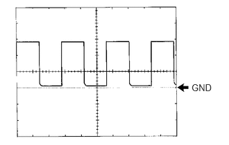
Using an oscilloscope, check waveform 1.
| Item | Condition |
|---|---|
| Terminal No. (Symbol) | E34-10 (REV) - Body ground |
| Tool setting | 5 V/DIV., 10 ms./DIV. |
| Condition | Engine idle speed |
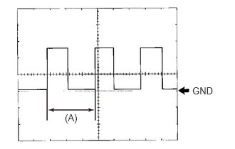
Using an oscilloscope, check waveform 2.
| Item | Condition |
|---|---|
| Terminal No. (Symbol) | ·
E34-12 (SPD1) - Body ground ·
E34-13 (SPSR) - Body ground |
| Tool setting | 5 V/DIV., 20 ms./DIV. |
| Condition | Being driven at approx. 20 km/h (12 mph) |
- HINT:
-
When the system is functioning normally, one wheel revolution generates 4 pulses. As the vehicle speed increases, the width indicated by (A) in the illustration narrows.
CHECK COMBINATION METER INNER CIRCUIT