Home › Vehicle Interior › HEATING / AIR CONDITIONING › AIR CONDITIONING PANEL
RM19Y0E _58 Vehicle Interior _003013 HEATING / AIR CONDITIONING _0015236 AIR CONDITIONING PANEL G

HEATING / AIR CONDITIONING  AIR CONDITIONING PANEL  INSPECTION  


PROCEDURE

Hide 55910R 1.INSPECT HEATER CONTROL ASSEMBLY

a.

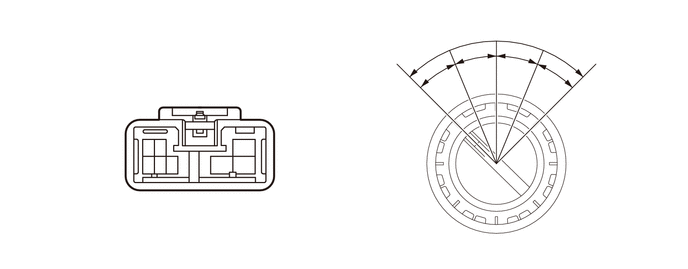
Check the heater control resistance (for Blower Switch).
E258201
1.177,0.604 1.573,0.875 0.396,0.271 10 *a 2.49,1.458 2.646,1.656 0.156,0.198 10 1 1.625,1.448 1.74,1.625 0.115,0.177 10 2 1.51,1.448 1.625,1.625 0.115,0.177 10 3 2.5,1.635 2.656,1.833 0.156,0.198 10 4 2.26,1.625 2.417,1.823 0.156,0.198 10 5 1.5,1.646 1.594,1.958 0.094,0.313 10 8 1.625,1.646 1.719,1.958 0.094,0.313 10 7 1.76,1.646 1.854,1.958 0.094,0.313 10 6 4.021,0.469 4.333,0.667 0.313,0.198 10 *b 4.552,0.313 4.865,0.51 0.313,0.198 10 *c 5.063,0.208 5.375,0.406 0.313,0.198 10 *d 5.615,0.333 5.927,0.531 0.313,0.198 10 *e 6.219,0.469 6.531,0.667 0.313,0.198 10 *f 4.49,0.823 4.833,1.042 0.344,0.219 10 22.5° 4.833,0.656 5.177,0.875 0.344,0.219 10 22.5° 5.198,0.646 5.542,0.865 0.344,0.219 10 22.5° 5.552,0.844 5.896,1.063 0.344,0.219 10 22.5°
*a Component without harness connected
(Heater Control Assembly)
*b OFF
*c L *d M, M1
*e M2 *f H


i.

Using an ohmmeter, measure the resistance and check the results in accordance with the values in the table below.

Standard Resistance:
Switch Position Tester Connection Specified Condition
OFF ALL - 1 10 kΩ or higher
L 1 - 8 Below 1 Ω
M.M1 1 - 8 - 6 10 kΩ or higher
M2 1 - 8 - 5 10 kΩ or higher
H 1 - 8 - 4 Below 1 Ω


If the result is not as specified, replace the heater control assembly.


b.

Check the illumination operation.

i.

Connect the positive (+) lead from the battery to terminal 7 and the negative (-) lead to terminal 6, then check that the bulb illuminates.

OK:

Bulb illuminates


If the result is not as specified, replace the bulb.


c.

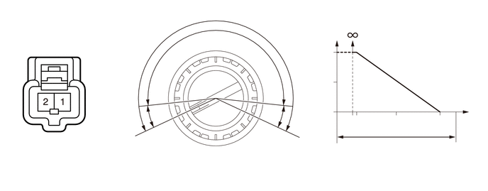
Check the heater control resistance (for A/C Volume).
E258202
0.188,0.167 0.844,0.615 0.656,0.448 10 *a 4.542,0.208 5.24,0.583 0.698,0.375 10 *d 2.99,0.115 3.948,0.594 0.958,0.479 10 230° 2.198,1.615 2.813,2.135 0.615,0.521 10 19.2° 3.802,1.625 4.51,2.125 0.708,0.5 10 19.2° 1.969,2.031 2.281,2.229 0.313,0.198 10 *b 4.25,2.021 4.563,2.219 0.313,0.198 10 *c 6.365,1.229 6.677,1.427 0.313,0.198 10 *e 4.896,2.146 5.208,2.344 0.313,0.198 10 *b 6.688,2.146 7,2.344 0.313,0.198 10 *c 5.719,2.052 6.344,2.406 0.625,0.354 10 270° 5.094,1.719 5.354,1.896 0.26,0.177 10 10° 5.708,1.74 6.104,1.927 0.396,0.188 10 135° 6.344,1.729 6.823,2.063 0.479,0.333 10 260°
*a Component without harness connected
(Heater Control Assembly)
*b OFF
*c MAX COOL *d Resistance (kΩ)
*e Rotation Angle - -


i.

Using an ohmmeter, measure the resistance variation between connector terminals 1 and 2 when the dial is turned as shown in the illustration.

OK:

Varies as shown in the illustration


Hide 88660C 2.INSPECT COOLER CONTROL SWITCH ASSEMBLY (w/ Heater)
a.
E239524
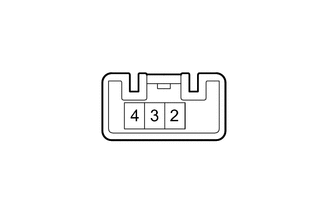
1.344,1.292 0.906,1.667 true 1.604,1.292 1.438,1.625 true 1.823,1.292 1.771,1.656 true 0.167,0.073 0.583,0.427 0.417,0.354 10 *a 0.854,1.667 1.063,1.875 0.208,0.208 10 - 1.708,1.708 2.135,2.125 0.427,0.417 10 +B 1.385,1.667 1.677,1.938 0.292,0.271 10 -
*a Component without harness connected
(Cooler Control Switch Assembly)


Check the cooler control switch assembly resistance.

i.

Using an ohmmeter, measure the resistance and check the results in accordance with the values in the table below.

Standard Resistance:
Switch Position Tester Connection Specified Condition
OFF 2 (+B) - 3 (-)
2 (+B) - 4 (-)
1 MΩ or higher
ON 2 (+B) - 4 (-) Below 1 Ω