RM19Y0E
_59
Vehicle Exterior
_003016
WINDOW / GLASS
_0015249
POWER WINDOW MASTER SWITCH
G
WINDOW / GLASS POWER WINDOW MASTER SWITCH INSPECTION
PROCEDURE

 84820
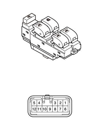
1.INSPECT POWER WINDOW REGULATOR MASTER SWITCH ASSEMBLY (for RHD)
a.
1.125,0.531 0.563,0.344
true
1.854,0.74 2.469,0.458
true
2.51,1.146 2.896,0.958
true
1.292,2.094 2.156,1.365
true
0.708,1.531 1.469,0.99
true
2.365,3.583 2.771,3.323
true
2.146,3.552 2.385,3.229
true
1.948,3.542 1.802,3.219
true
1.365,3.563 1.219,3.24
true
1.135,3.563 0.719,3.354
true
1.146,3.906 0.74,4.073
true
2.375,3.896 2.771,4.135
true
1.396,3.927 1.302,4.333
true
1.604,3.917 1.698,4.344
true
2.146,3.927 2.26,4.354
true
0.344,0.25 0.854,0.635
0.51,0.385
10
*1
2.531,0.365 3.094,0.719
0.563,0.354
10
*2
0.469,1.479 1.01,1.823
0.542,0.344
10
*3
2.99,0.865 3.396,1.198
0.406,0.333
10
*4
1.146,2.156 1.719,2.49
0.573,0.333
10
*5
0.188,2.729 0.781,3.083
0.594,0.354
10
*a
2.844,3.208 3.323,3.5
0.479,0.292
10
IG
2.302,3.063 2.781,3.354
0.479,0.292
10
RRU+
1.635,3.042 2.115,3.333
0.479,0.292
10
RRD+
1.042,3.063 1.521,3.354
0.479,0.292
10
RLD+
0.323,3.26 0.802,3.552
0.479,0.292
10
RLU+
0.396,4 0.875,4.292
0.479,0.292
10
PD+
2.865,4.083 3.344,4.375
0.479,0.292
10
E
1.135,4.375 1.615,4.667
0.479,0.292
10
M/D+
1.583,4.375 2.063,4.667
0.479,0.292
10
M/U+
2.198,4.375 2.677,4.667
0.479,0.292
10
PU+
| *1 | Window Lock Switch |
| *2 | Driver Switch |
| *3 | Front Passenger Switch |
| *4 | Rear RH Side Switch |
| *5 | Rear LH Side Switch |
| *a | Component without harness connected
(Power Window Regulator Master Switch Assembly) |
Check that the resistance.
i.
Measure the resistance according to the value(s) in the table below.
- Standard resistance:
- Passenger Side Switch:
Window Lock Switch Condition Power Window Switch condition Tester connection Specified condition OFF UP 1 (IG) - 7 (PU+)
12 (PD+) - 6 (E)Below 1 Ω OFF OFF 7 (PU+) - 6 (E)
12 (PD+) - 6 (E)Below 1 Ω OFF DOWN 1 (IG) - 12 (PD+)
7 (PU+) - 6 (E)Below 1 Ω ON UP 1 (IG) - 7 (PU+) Below 1 Ω ON OFF 7 (PU+) - 12 (PD+) Below 1 Ω ON DOWN 1 (IG) - 12 (PD+) Below 1 Ω
- Standard resistance:
- Rear RH Side Switch:
Window Lock Switch Condition Power Window Switch condition Tester connection Specified condition OFF UP 1 (IG) - 2 (RRU+)
3 (RRD+) - 6 (E)Below 1 Ω OFF OFF 2 (RRU+) - 6 (E)
3 (RRD+) - 6 (E)Below 1 Ω OFF DOWN 1 (IG) - 3 (RRD+)
2 (RRU+) - 6 (E)Below 1 Ω ON UP 1 (IG) - 2 (RRU+) Below 1 Ω ON OFF 2 (RRU+) - 3 (RRD+) Below 1 Ω ON DOWN 1 (IG) - 3 (RRD+) Below 1 Ω
- Standard resistance:
- Rear LH Side Switch:
Window Lock Switch Condition Power Window Switch condition Tester connection Specified condition OFF UP 1 (IG) - 5 (RLU+)
4 (RLD+) - 6 (E)Below 1 Ω OFF OFF 5 (RLU+) - 6 (E)
4 (RLD+) - 6 (E)Below 1 Ω OFF DOWN 1 (IG) - 4 (RLD+)
5 (RLU+) - 6 (E)Below 1 Ω ON UP 1 (IG) - 5 (RLU+) Below 1 Ω ON OFF 5 (RLU+) - 4 (RLD+) Below 1 Ω ON DOWN 1 (IG) - 4 (RLD+) Below 1 Ω
b.
Check the illumination operation.
i.
Apply battery voltage to the power window regulator master switch and check that the illumination comes on.
- OK:
Measurement Condition Specified Condition Battery positive (+) → Terminal 1 (IG)
Battery negative (-) → Terminal 6 (E)Illumination comes on
84820
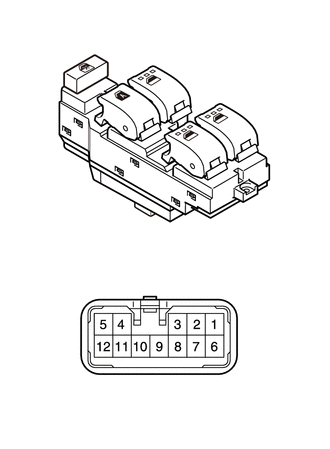
2.INSPECT POWER WINDOW REGULATOR MASTER SWITCH ASSEMBLY (for LHD)
a.
0.948,0.615 0.656,0.365
true
1.75,0.813 2.01,0.51
true
2.49,1.24 2.781,0.979
true
1.625,2.427 2.042,1.531
true
0.563,1.667 1.375,1.125
true
0.698,3.198 1.01,3.313
true
1.01,2.969 1.219,3.292
true
1.823,3.292 1.667,2.979
true
2.01,3.292 2.281,2.958
true
2.302,3.323 2.656,3.208
true
2.281,3.677 2.688,3.823
true
1.49,3.667 1.75,4.073
true
1.25,3.688 1.219,4.094
true
0.729,3.948 1.01,3.688
true
2.271,4.042 2.063,3.698
true
0.438,0.24 0.75,0.438
0.313,0.198
10
*1
0.458,1.708 0.771,1.906
0.313,0.198
10
*2
2.104,0.406 2.417,0.604
0.313,0.198
10
*3
2.854,0.896 3.167,1.094
0.313,0.198
10
*4
1.583,2.469 1.896,2.667
0.313,0.198
10
*5
0.135,2.635 0.448,2.833
0.313,0.198
10
*a
0.813,2.792 1.427,2.99
0.615,0.198
10
RRD+
1.49,2.781 2.104,2.979
0.615,0.198
10
RLD+
2.198,2.792 2.656,2.99
0.458,0.198
10
PU+
2.698,3.104 3.01,3.302
0.313,0.198
10
IG
2.75,3.781 2.906,3.979
0.156,0.198
10
E
2.271,4.094 2.885,4.292
0.615,0.198
10
RLU+
1.635,4.135 2.25,4.333
0.615,0.198
10
M/U+
1.042,4.115 1.656,4.313
0.615,0.198
10
M/D+
0.323,3.99 0.938,4.188
0.615,0.198
10
RRU+
0.385,3.073 0.844,3.271
0.458,0.198
10
PD+
| *1 | Window Lock Switch |
| *2 | Driver Switch |
| *3 | Front Passenger Switch |
| *4 | Rear RH Side Switch |
| *5 | Rear LH Side Switch |
| *a | Component without harness connected
(Power Window Regulator Master Switch Assembly) |
Check that the resistance.
i.
Measure the resistance according to the value(s) in the table below.
- Standard resistance:
- Passenger Side Switch:
Window Lock Switch Condition Power Window Switch condition Tester connection Specified condition OFF UP 1 (IG) - 2 (PU+)
5 (PD+) - 6 (E)Below 1 Ω OFF OFF 2 (PU+) - 6 (E)
5 (PD+) - 6 (E)Below 1 Ω OFF DOWN 1 (IG) - 5 (PD+)
2 (PU+) - 6 (E)Below 1 Ω ON UP 1 (IG) - 2 (PU+) Below 1 Ω ON OFF 2 (PU+) - 5 (PD+) Below 1 Ω ON DOWN 1 (IG) - 5 (PD+) Below 1 Ω
- Standard resistance:
- Rear RH Side Switch:
Window Lock Switch Condition Power Window Switch condition Tester connection Specified condition OFF UP 1 (IG) - 12 (RRU+)
4 (RRD+) - 6 (E)Below 1 Ω OFF OFF 12 (RRU+) - 6 (E)
4 (RRD+) - 6 (E)Below 1 Ω OFF DOWN 1 (IG) - 4 (RRD+)
12 (RRU+) - 6 (E)Below 1 Ω ON UP 1 (IG) - 12 (RRU+) Below 1 Ω ON OFF 12 (RRU+) - 4 (RRD+) Below 1 Ω ON DOWN 1 (IG) - 4 (RRD+) Below 1 Ω
- Standard resistance:
- Rear LH Side Switch:
Window Lock Switch Condition Power Window Switch condition Tester connection Specified condition OFF UP 1 (IG) - 7 (RLU+)
3 (RLD+) - 6 (E)Below 1 Ω OFF OFF 7 (RLU+) - 6 (E)
3 (RLD+) - 6 (E)Below 1 Ω OFF DOWN 1 (IG) - 3 (RLD+)
7 (RLU+) - 6 (E)Below 1 Ω ON UP 1 (IG) - 7 (RLU+) Below 1 Ω ON OFF 7 (RLU+) - 3 (RLD+) Below 1 Ω ON DOWN 1 (IG) - 3 (RLD+) Below 1 Ω
b.
Check the illumination operation.
i.
Apply battery voltage to the power window regulator master switch and check that the illumination comes on.
- OK:
Measurement Condition Specified Condition Battery positive (+) → Terminal 1 (IG)
Battery negative (-) → Terminal 6 (E)Illumination comes on