RM19Y0E
_59
Vehicle Exterior
_003018
MIRROR (EXT)
_0015270
OUTER MIRROR SWITCH
G
MIRROR (EXT) OUTER MIRROR SWITCH INSPECTION
PROCEDURE

 84870A
1.INSPECT OUTER MIRROR SWITCH ASSEMBLY
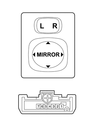
a.
Check the resistance.
i.
Select "L" on the left/right adjustment switch.
ii.
Using an ohmmeter, measure the resistance and check the results in accordance with the value(s) in the table below.
- Standard Resistance:
Tester Connection Switch Condition Specified Condition 7 (B) - 6 (E) OFF 10 kΩ or higher 3 (VL) - 7 (B)
5 (C) - 6 (E)UP Below 1 Ω 3 (VL) - 6 (E)
5 (C) - 7 (B)DOWN Below 1 Ω 4 (HL) - 7 (B)
5 (C) - 6(E)LEFT Below 1 Ω 4 (HL) - 6 (E)
5 (C) - 7 (B)RIGHT Below 1 Ω
If the result is not as specified, replace the outer mirror switch assembly.
iii.
Select "R" on the left/right adjustment switch.
iv.
Using an ohmmeter, measure the resistance and check the results in accordance with the value(s) in the table below.
- Standard Resistance:
Tester Connection Switch Condition Specified Condition 7 (B) - 6 (E) OFF 10 kΩ or higher 2 (VR) - 7 (B)
5 (C) - 6 (E)UP Below 1 Ω 2 (VR) - 6 (E)
5 (C) - 7 (B)DOWN Below 1 Ω 1 (HR) - 7 (B)
5 (C) - 6 (E)LEFT Below 1 Ω 1 (HR) - 6 (E)
5 (C) - 7 (B)RIGHT Below 1 Ω
If the result is not as specified, replace the outer mirror switch assembly.