RM19Y0E
_58
Vehicle Interior
_003013
HEATING / AIR CONDITIONING
_0015224
AIR CONDITIONING SYSTEM
U
HEATING / AIR CONDITIONING AIR CONDITIONING SYSTEM TERMINALS OF ECU
CHECK ECM
3.323,0.073 3.719,0.313
0.396,0.24
1.667,0.063 2.063,0.302
0.396,0.24
5.219,0.073 5.615,0.313
0.396,0.24
3.396,0.115 3.688,0.271
0.292,0.156
10
C24
1.75,0.115 2.042,0.271
0.292,0.156
10
C23
5.323,0.115 5.615,0.271
0.292,0.156
10
E3
- HINT:
-
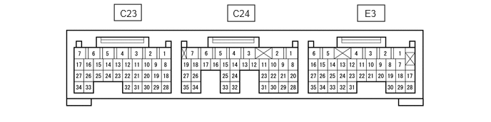
The standard normal voltage between each pair of ECM terminals is shown in the table below. The appropriate conditions for checking each pair of terminals are also indicated. The result of checks should be compared with the standard normal voltage for that pair of terminals, displayed in the STD Voltage column. The illustration above can be used as a reference to identify the ECM terminal locations.
| Symbols (Terminal No.) | Wiring Color | Terminal Description | Condition | Specified Condition |
|---|---|---|---|---|
| BAT (E3-7) - E1 (C24-32) | B - W-B | Battery (for measuring battery voltage and for ECM memory) | Always | 11 to 14 V |
| +B1 (C23-7) - E1 (C24-32) | L - W-B | Power source of ECM | Ignition switch ON | 11 to 14 V |
| ACEV (E3-14) - E21 (E3-31) | W-R - R-G | No. 1 cooler thermistor (A/C evaporator temperature sensor) | Air conditioner ON | 0.15 to 4.8 V |
| ACSW (E3-29) - E1 (C24-32) | L-Y - W-B | A/C pressure switch*1 | Ignition switch ON | 11 to 14 V |
| A/C pressure switch and air conditioning switch*2 | Engine idling, Blower switch ON and air conditioning switch ON | 11 to 14 V | ||
| Power supply for air conditioner*3 | Ignition switch ON | 11 to 14 V | ||
| ACVR (E3-30) - E21 (E3-31)*1 | B-Y - R-G | A/C volume switch (Heater control assembly) | Ignition switch ON | Varies with volume |
| MGC (E3-15) - E01 (C24-7) | G-W - W-B | A/C magnet clutch | A/C Magnetic clutch ON | Below 1.0 V |
| A/C Magnetic clutch OFF | 11 to 14 V | |||
| BLW (E3-11) - E1 (C24-32) | L-R - W-B | Blower motor | Blower switch ON | Below 0.5 V |
| Blower switch OFF | 11 to 14 V | |||
| FAN (E3-16) - E01 (C24-7) | R-W - W-B | Radiator fan | Radiator fan ON | Below 1.0 V |
| Radiator fan OFF | 11 to 14 V | |||
| FAN2 (E3-5) - E01 (C24-7)*3 | R - W-B | RAD No. 2 relay | Engine coolant temperature is 97 °C (207 °F) or lower, or engine speed is 1500 rpm or lower | 11 to 14 V |
| Engine coolant temperature is higher than 100 °C (212 °F) and engine speed is 1700 rpm or higher | Below 1.0 V | |||
| VCO (C24-21) - E24 (C24-27)*3 | G - W | Power supply for air conditioner pressure sensor | Ignition switch ON | 4.75 to 5.25 V |
| ACAD (C24-26) - E24 (C24-27)*3 | R - W | Air conditioner pressure sensor | Refrigerant pressure:
0 MPa (0 kgf/cm2, 0 psi) →3.187 MPa (32.5 kgf/cm2, 462 psi) |
0.39 V → 4.95 V |
| E24 (C24-27) - Body ground*3 | W - Body ground | Ground | Always | Below 1 Ω |
| E1 (C24-32) - Body ground | W-B - Body ground | Ground | Always | Below 1 Ω |
| E21 (E3-31) - Body ground | R-G - Body ground | |||
| E01 (C24-7) - Body ground | W-B - Body ground |
*1 : w/o Heater
*2 : w/ Heater
*3 : w/ Cooling Fan Resister
If the result is not as specified, there may be a malfunction on the wire harness side.