HEATING / AIR CONDITIONING AIR CONDITIONING PRESSURE SENSOR ON-VEHICLE INSPECTION
PROCEDURE

 88719A
1.INSPECT AIRCONDITIONER PRESSURE SENSOR (for 3 Pin Connector Type)
Check the wire harness.
Disconnect the connector from the airconditioner pressure sensor.
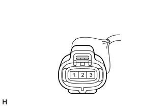
| *a | Front view of wire harness connector
(to Airconditioner Pressure Sensor) |
Measure the resistance between connector terminal 1 (E) of the airconditioner pressure sensor and body ground.
- Standard Resistance:
Tester Connection Condition Specified Condition B18-1 (E) - Body ground Always Below 1 Ω
Turn the ignition switch to ON.
| *a | Front view of wire harness connector
(to Airconditioner Pressure Sensor) |
Measure the voltage according to the value(s) in the table below.
- Standard Voltage:
Tester Connection Switch Condition Specified Condition B18-3 (VC) - B18-1 (E) Ignition switch ON 4.75 to 5.25 V
Check the airconditioner pressure sensor.
Set the manifold gauge.
Warm up the engine.
Turn the A/C switch on.
When applying 5 V between the connector terminals 3 (VC) and 1 (E) of the airconditioner pressure sensor, measure the voltage between terminals 2 (VOUT) and 1 (E).
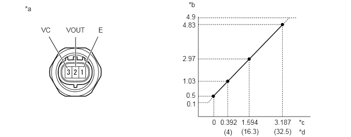
| *a | Component without harness connected
(Airconditioner Pressure Sensor) |
*b | Voltage (V) |
| *c | Mpa | *d | kgf/cm2 |
- OK:
The transition of the pressure is as shown in the illustration due to the refrigerant pressure.
88645H
2.INSPECT NO. 1 PRESSURE SWITCH (for 2 Pin Connector Type)
Check the wire harness.
Disconnect the connector of the No. 1 pressure switch.
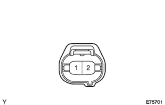
| *a | Front view of wire harness connector
(to No. 1 Pressure Switch) |
Using a service wire, connect terminals 1 and 2 of the No. 1 pressure switch connector on the vehicle wire harness side.
Start the engine.
Turn the A/C switch on and check that the magnet clutch turns on.
Check that the magnet clutch turns off when disconnecting terminals 1 and 2.
- OK:
Measurement Condition Specified Condition Terminals 1 and 2 connected Magnet clutch turns on Terminals 1 and 2 disconnected Magnet clutch turns off