BRAKE SYSTEM (OTHER) BRAKE PEDAL(for RHD) INSTALLATION
PROCEDURE

 55106
1.INSTALL BRAKE PEDAL SUPPORT SUB-ASSEMBLY
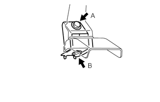
Temporarily install the brake pedal mounting bracket with the bolt A.
Temporarily install bolt B.
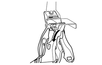
Hook and hold the brake pedal support sub-assembly onto the bolt B used for the temporary installation.
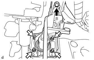

|
Bolt |

|
Nut |
Install the brake pedal support sub-assembly with the bolt B and 4 nuts.
- Torque:
- Bolt B : 21 N*m (214 kgf*cm, 15 ft.*lbf)
- Nut : 12.8 N*m (131 kgf*cm, 9 ft.*lbf)
Tighten the bolt A.
- Torque:
- 31 N*m (316 kgf*cm, 23 ft.*lbf)
47264D
2.INSTALL BRAKE MASTER CYLINDER PUSH ROD CLEVIS
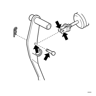
|
|
Lithium soap base glycol grease |
Apply lithium soap base glycol grease to the push rod pin, push rod clevis hole and brake pedal hole.
Install the brake master cylinder push rod clevis with the push rod pin and clip.
84345
3.INSTALL STOP LIGHT SWITCH MOUNTING ADJUSTER
Install the stop light switch mounting adjuster onto the pedal support sub-assembly.
84340
4.INSTALL STOP LIGHT SWITCH ASSEMBLY
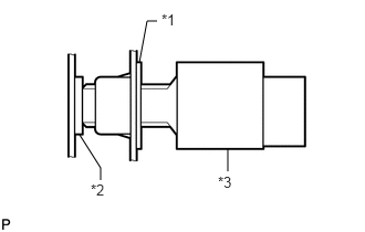
| *1 | Adjuster |
| *2 | Cushion |
| *3 | Stop light switch assembly |
Insert the stop light switch assembly into the adjuster until it just touches the stop light switch cushion.
- NOTICE:
-
Do not depress the brake pedal.
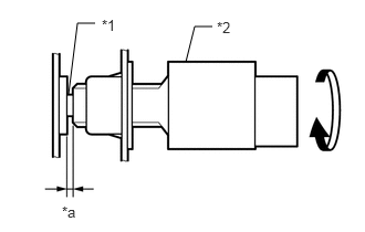
| *1 | Shaft |
| *2 | Stop light switch assembly |
| *a | 0.2 to 2.8 mm
(0.008 to 0.110 in.) |
Turn the stop light switch assembly 90° clockwise to install it.
- NOTICE:
-
Do not depress the brake pedal.
Check the stop light switch assembly clearance.
- Stop light switch clearance:
0.2 to 2.8 mm (0.008 to 0.110 in.)
Connect the connector to the stop light switch assembly.
47101
5.INSPECT AND ADJUST BRAKE PEDAL SUB-ASSEMBLY
45287
6.INSTALL LOWER STEERING COLUMN COVER
83100
7.INSTALL COMBINATION METER ASSEMBLY