Home › Vehicle Interior › INTERIOR PANELS / TRIM › UPPER INSTRUMENT PANEL › from 2015.08
RM19Y0E _58 Vehicle Interior _003015 INTERIOR PANELS / TRIM _0015243 UPPER INSTRUMENT PANEL A

INTERIOR PANELS / TRIM  UPPER INSTRUMENT PANEL  REASSEMBLY  


PROCEDURE

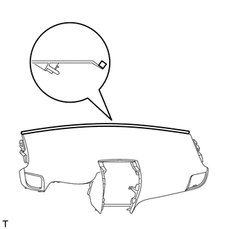
Hide 55355 1.INSTALL NO. 1 INSTRUMENT PANEL CUSHION
a.
B297356

Remove the peeling paper from a new No. 1 instrument panel cushion.


b.

Install the new No. 1 instrument panel cushion as shown in the illustration.
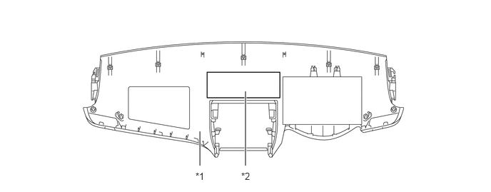

Hide 55357B 2.INSTALL NO. 3 INSTRUMENT PANEL CUSHION

a.

Remove the peeling paper from a new No. 3 instrument panel cushion.


b.

Install the new No. 3 instrument panel cushion as shown in the illustration.
B415890C01
2.917,2.417 2.917,1.917 true 3.583,2.417 3.583,1.333 true 2.854,2.49 3.167,2.646 0.313,0.156 10 false *1 3.521,2.49 3.833,2.646 0.313,0.156 10 false *2
*1 Instrument Panel Sub-assembly *2 No. 3 Instrument Panel Cushion


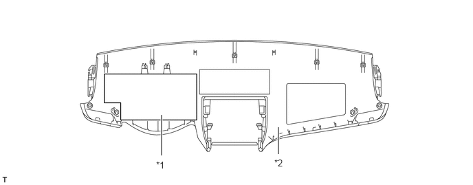
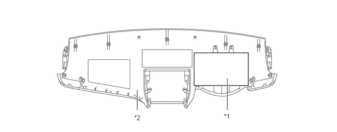
Hide 55356C 3.INSTALL NO. 2 INSTRUMENT PANEL CUSHION

a.

for RHD:

i.

Remove the peeling paper from a new No. 2 instrument panel cushion.


ii.

Install the new No. 2 instrument panel cushion as shown in the illustration.
B346640C03
2.448,2.354 2.448,1.74 true 4.219,2.333 4.219,1.927 true 2.365,2.417 2.719,2.688 0.354,0.271 10 false *1 4.156,2.385 4.51,2.656 0.354,0.271 10 false *2
*1 No. 2 Instrument Panel Cushion *2 Instrument Panel Sub-assembly


b.

for LHD:

i.

Remove the peeling paper from a new No. 2 instrument panel cushion.


ii.

Install the new No. 2 instrument panel cushion as shown in the illustration.

B415889C01
4.833,2.333 4.833,1.667 true 2.917,2.333 2.917,1.917 true 4.76,2.385 5.073,2.542 0.313,0.156 10 false *1 2.854,2.417 3.167,2.573 0.313,0.156 10 false *2
*1 No. 2 Instrument Panel Cushion *2 Instrument Panel Sub-assembly


Hide 55650 4.INSTALL NO. 1 INSTRUMENT PANEL REGISTER ASSEMBLY
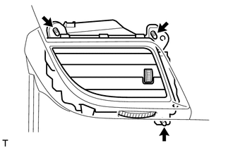
a.
B297353

Install the No. 1 instrument panel register assembly with the 3 screws.


Hide 55660 5.INSTALL NO. 2 INSTRUMENT PANEL REGISTER ASSEMBLY

HINT:

Use the same procedure for the No. 1 instrument panel register assembly.


Hide 87223A 6.INSTALL AIR DUCT PAD

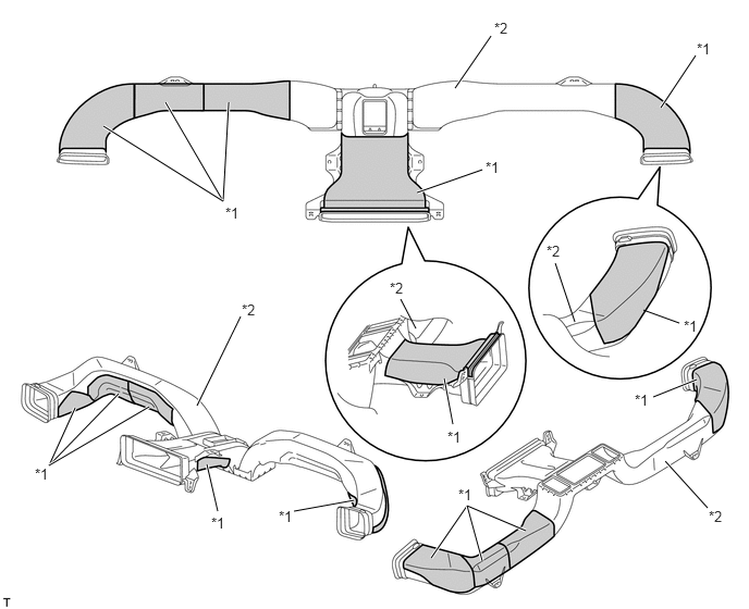
a.

for LHD

i.

Remove the peeling paper from the 5 new air duct pads.


ii.

Install the 5 new air duct pads as shown in the illustration.
B297352C02
4.354,0.844 4.698,0.344 true 3.99,1.844 4.615,1.625 true 6.323,1.031 6.656,0.531 true 5.5,3.083 5.313,2.521 false 6.156,2.969 6.5,3.094 false 3.979,3.146 3.833,2.865 false 4.333,4.063 4.25,3.625 true 6.25,3.802 6.667,3.635 true 6.771,4.865 6.365,4.417 true 4.125,5.344 4.469,4.844 true 4.615,5.375 4.469,4.844 4.469,4.844 5.031,5.083 true 3.385,4.792 2.813,4.896 true 2.083,4.896 1.979,4.448 true 0.719,3.906 0.469,4.458 0.469,4.458 1.135,3.771 true 1.427,3.896 0.469,4.458 true 1.885,3.885 2.302,3.031 true 2.188,0.979 2.135,1.927 2.135,1.927 1.583,0.979 true 0.99,1.208 2.135,1.927 true 2.156,1.958 2.479,2.24 0.323,0.281 10 *1 4.281,4.104 4.594,4.375 0.313,0.271 10 *1 4.646,1.521 5,1.813 0.354,0.292 10 *1 6.542,3.042 6.885,3.333 0.344,0.292 10 *1 6.667,0.385 6.969,0.688 0.302,0.302 10 *1 4.385,4.656 4.688,4.938 0.302,0.281 10 *1 6.073,3.75 6.385,4.063 0.313,0.313 10 *1 2.667,4.865 2.958,5.125 0.292,0.26 10 *1 0.333,4.458 0.719,4.792 0.385,0.333 10 *1 2.021,4.927 2.333,5.188 0.313,0.26 10 *1 4.729,0.188 5.052,0.5 0.323,0.313 10 *2 3.729,2.677 4.031,2.958 0.302,0.281 10 *2 5.229,2.323 5.563,2.625 0.333,0.302 10 *2 6.781,4.865 7.104,5.188 0.323,0.323 10 *2 2.313,2.885 2.625,3.177 0.313,0.292 10 *2
*1 Air Duct Pad *2 Center Heater to Register Duct Sub-assembly


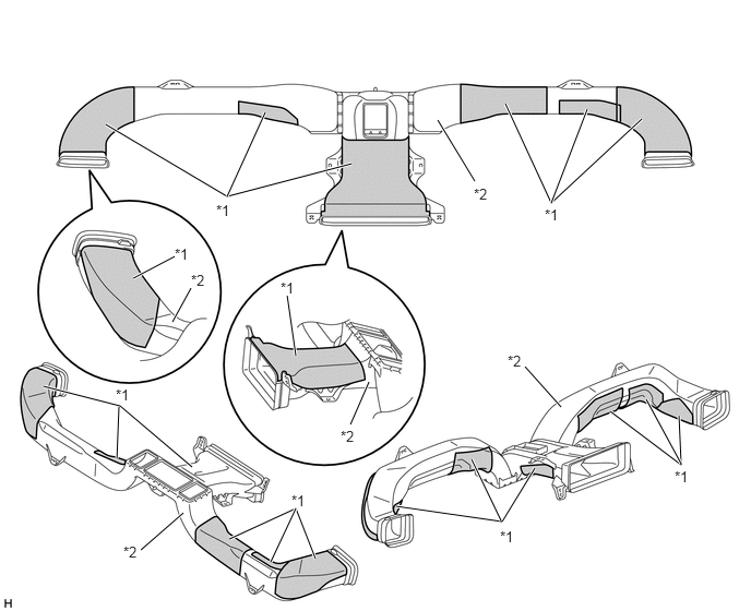
b.

for RHD

i.

Remove the peeling paper from the 6 new air duct pads.


ii.

Install the 6 new air duct pads as shown in the illustration.
B291090C04
1.01,1.188 2.167,1.875 2.167,1.875 3.354,1.563 true 2.531,1.073 2.167,1.875 true 4.823,0.99 5.26,1.938 5.26,1.938 6.125,1.135 true 5.604,1.042 5.26,1.938 true 2.823,3.396 2.74,2.823 true 1.271,2.656 1.667,2.448 true 0.417,3.688 1.146,3.875 1.146,3.875 1.833,4.458 true 1.115,4.375 1.135,3.885 true 2.188,5.146 2.823,4.854 2.823,4.854 3.01,5.333 true 2.583,5.365 2.823,4.854 true 3.781,4.833 4.792,4.979 4.792,4.979 5.104,4.469 true 4.781,4.969 4.5,4.385 true 5.823,3.927 6.5,4.438 6.5,4.438 6.479,3.969 true 6.167,3.813 6.5,4.427 true 1.344,5.25 1.75,4.896 true 5.01,3.5 5.354,3.885 true 3.344,4.052 3.521,3.646 true 1.646,3.073 1.823,2.75 true 4.531,1.729 4.177,1.146 true 5.198,1.969 5.646,2.396 0.448,0.427 10 *1 2.063,1.927 2.542,2.281 0.479,0.354 10 *1 2.677,2.667 3.135,3.01 0.458,0.344 10 *1 1.667,2.344 2.094,2.74 0.427,0.396 10 *1 1.104,3.688 1.573,4.063 0.469,0.375 10 *1 2.781,4.698 3.156,5.021 0.375,0.323 10 *1 4.771,5.042 5.344,5.521 0.573,0.479 10 *1 6.438,4.469 6.969,4.958 0.531,0.49 10 *1 4.844,3.365 5.281,3.719 0.438,0.354 10 *2 3.25,4.083 3.729,4.438 0.479,0.354 10 *2 4.521,1.771 4.969,2.125 0.448,0.354 10 *2 1.823,2.594 2.219,2.875 0.396,0.281 10 *2 1.177,5.188 1.823,5.635 0.646,0.448 10 *2
*1 Air Duct Pad *2 Center Heater to Register Duct Sub-assembly


Hide 55086A 7.INSTALL CENTER HEATER TO REGISTER DUCT SUB-ASSEMBLY

a.

Install the center heater to register duct sub-assembly with the 4 screws.
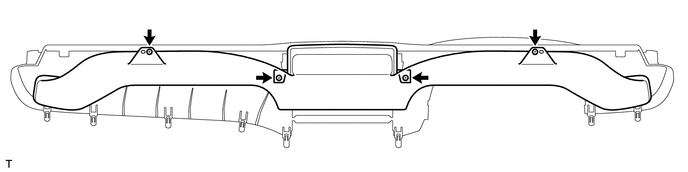
B297351


Hide 55981 8.INSTALL NO. 1 DEFROSTER NOZZLE GARNISH (w/ Heater)
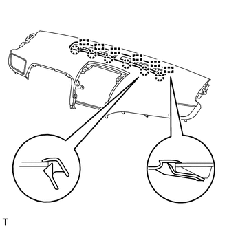
a.
B297400

Engage the 6 guides and 6 claws to install the No. 1 defroster nozzle garnish.


Hide 55950G 9.INSTALL DEFROSTER NOZZLE ASSEMBLY (w/ Heater)

a.

Install the defroster nozzle assembly with the 3 screws.
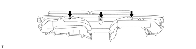
B297399