RM19Y0E
_58
Vehicle Interior
_003013
HEATING / AIR CONDITIONING
_0015235
AIR CONDITIONING PRESSURE SENSOR
G
HEATING / AIR CONDITIONING AIR CONDITIONING PRESSURE SENSOR ON-VEHICLE INSPECTION
PROCEDURE

 88719A
1.INSPECT AIRCONDITIONER PRESSURE SENSOR
a.
Check the wire harness.
i.
Disconnect the connector from the airconditioner pressure sensor.
ii.
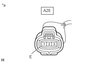
1.417,0.25 1.833,0.5
0.417,0.25
1.448,1.573 1.083,1.865
true
0.063,0.094 0.375,0.25
0.313,0.156
10
false
*a
1.01,1.885 1.323,2.083
0.313,0.198
10
false
E
1.49,0.281 1.948,0.521
0.458,0.24
10
false
A28
| *a | Front view of wire harness connector
(to Airconditioner Pressure Sensor) |
Measure the resistance between connector terminal 1 (E) of the airconditioner pressure sensor and body ground.
- Standard Resistance:
Tester Connection Condition Specified Condition A28-1 (E) - Body ground Always Below 1 Ω
iii.
Turn the ignition switch to ON.
iv.
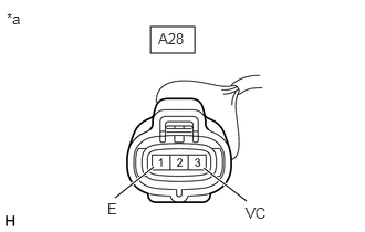
1.417,0.25 1.833,0.5
0.417,0.25
1.448,1.573 1.083,1.865
true
1.917,1.583 2.323,1.896
true
0.063,0.094 0.375,0.25
0.313,0.156
10
false
*a
2.313,1.927 2.625,2.125
0.313,0.198
10
false
VC
1.01,1.885 1.323,2.083
0.313,0.198
10
false
E
1.49,0.281 1.948,0.521
0.458,0.24
10
false
A28
| *a | Front view of wire harness connector
(to Airconditioner Pressure Sensor) |
Measure the voltage according to the value(s) in the table below.
- Standard Voltage:
Tester Connection Switch Condition Specified Condition A28-3 (VC) - A28-1 (E) Ignition switch ON 4.75 to 5.25 V
b.
Check the airconditioner pressure sensor.
i.
Set the manifold gauge.
ii.
Warm up the engine.
iii.
Turn the A/C switch on.
iv.
When applying 5 V between the connector terminals 3 (VC) and 1 (E) of the airconditioner pressure sensor, measure the voltage between terminals 2 (VOUT) and 1 (E).
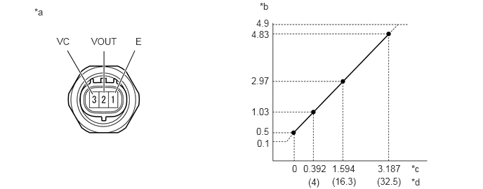
1.708,1.375 2,0.75
true
1.375,1.396 1,0.75
true
1.542,1.375 1.542,0.76
true
0.51,0.094 0.823,0.292
0.313,0.198
10
false
*a
0.844,0.531 1.156,0.729
0.313,0.198
10
false
VC
1.354,0.531 1.969,0.729
0.615,0.198
10
false
VOUT
2.01,0.531 2.167,0.729
0.156,0.198
10
false
E
3.854,0.01 4.167,0.208
0.313,0.198
10
false
*b
3.802,0.26 4.26,0.458
0.458,0.198
10
false
4.9
3.729,0.427 4.344,0.625
0.615,0.198
10
false
4.83
3.729,1.115 4.344,1.313
0.615,0.198
10
false
2.97
3.729,1.573 4.344,1.771
0.615,0.198
10
false
1.03
3.802,1.865 4.26,2.063
0.458,0.198
10
false
0.5
3.813,2.042 4.271,2.24
0.458,0.198
10
false
0.1
4.333,2.417 4.49,2.615
0.156,0.198
10
false
0
4.5,2.417 5.063,2.594
0.563,0.177
10
false
0.392
4.927,2.417 5.49,2.573
0.563,0.156
10
false
1.594
5.604,2.417 6.073,2.552
0.469,0.135
10
false
3.187
4.573,2.615 4.875,2.771
0.302,0.156
10
false
(4)
4.927,2.604 5.417,2.781
0.49,0.177
10
false
(16.3)
5.594,2.604 6.01,2.771
0.417,0.167
10
false
(32.5)
6.104,2.417 6.302,2.583
0.198,0.167
10
false
*c
6.104,2.615 6.302,2.781
0.198,0.167
10
false
*d
| *a | Component without harness connected
(Airconditioner Pressure Sensor) |
*b | Voltage (V) |
| *c | Mpa | *d | kgf/cm2 |
- OK:
The transition of the pressure is as shown in the illustration due to the refrigerant pressure.