RM19Y0E
_59
Vehicle Exterior
_003019
WIPER / WASHER
_0015271
WIPER AND WASHER SYSTEM
J
WIPER / WASHER WIPER AND WASHER SYSTEM Wiper Switch (HI Speed) Circuit
DESCRIPTION
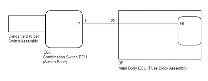
The base switch assembly transmits a wiper switch HI signal to the main body ECU (fuse block assembly) using CAN communication and via a direct line.
WIRING DIAGRAM
0.292,1.167 1.469,1.667
1.177,0.5
10
false
Windshield Wiper Switch Assembly
1.5,1.719 1.99,1.969
0.49,0.25
10
false
E68
1.479,1.885 3.052,2.604
1.573,0.719
10
false
Combination Switch ECU (Switch Base)
2.688,0.74 3.104,0.948
0.417,0.208
10
false
2
2.896,0.625 4.24,0.865
1.344,0.24
10
false
1
3.823,0.625 4.281,0.823
0.458,0.198
10
false
22
4.083,2.271 6.917,2.604
2.833,0.333
10
false
Main Body ECU (Fuse Block Assembly)
4.094,2.094 4.552,2.292
0.458,0.198
10
false
3F
6.208,0.74 6.667,0.938
0.458,0.198
10
false
HI
PROCEDURE
1.CHECK HARNESS AND CONNECTOR (COMBINATION SWITCH ECU (SWITCH BASE) - MAIN BODY ECU (FUSE BLOCK ASSEMBLY))
a.
Disconnect the E68 combination switch ECU (switch base) connector.
b.
Disconnect the 3F main body ECU (fuse block assembly) connector.
c.
Measure the resistance according to the value(s) in the table below.
- Standard Resistance (Check for Open):
Tester Connection Condition Specified Condition E68-1 (2) - 3F-22 Always Below 1 Ω
- Standard Resistance (Check for Short):
Tester Connection Condition Specified Condition E68-1 (2) - Body ground Always 10 kΩ or higher 3F-22 - Body ground Always 10 kΩ or higher
- Result:
Proceed to OK NG
OK
PROCEED TO NEXT SUSPECTED AREA SHOWN IN PROBLEM SYMPTOMS TABLE
NG
REPAIR OR REPLACE HARNESS OR CONNECTOR