2NR-VE ENGINE CONTROL SFI SYSTEM(w/o Air Fuel Ratio Sensor) FREEZE FRAME DATA
DESCRIPTION
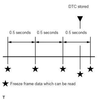
The ECM records vehicle and driving condition information as freeze frame data the moment a DTC is stored. When troubleshooting, freeze frame data can be helpful in determining whether the vehicle was moving or stationary, whether the engine was warmed up or not, whether the air fuel ratio was lean or rich, as well as other data recorded at the time of a malfunction.
- HINT:
-
If it is impossible to replicate the problem even though a DTC is detected, confirm the freeze frame data.
The ECM records engine conditions in the form of freeze frame data every 0.5 seconds. Using the GTS, 5 separate sets of freeze frame data can be checked.
3 data sets before the DTC was stored.
1 data set when the DTC was stored.
1 data set after the DTC was stored.
These data sets can be used to simulate the condition of the vehicle around the time of the occurrence the malfunction. The data may assist in identifying the cause of the malfunction, and judging whether it was temporary or not.
LIST OF FREEZE FRAME DATA
| Tester Display |
|---|
| Engine oil pressure SW |
| Power steering oil pressure |
| Stop lamp SW |
| Brake cancel SW |
| STA SW |
| Electric load signal 1 |
| Electric load signal 2 |
| Electric load signal 3 |
| Shift position P range |
| Shift position R range |
| Shift position N range |
| Shift position D range |
| Shift position 3 range |
| Shift position 2 range |
| Shift position L range |
| OD SW |
| Neutral start SW |
| AC SW |
| Test terminal |
| Purge VSV test |
| A/C magnet clutch relay test |
| OCV test |
| Electrical fan test |
| Purge VSV duty ratio |
| Fr O2 sensor heater current |
| Fr O2 sensor heater operation |
| Electrical fan high operation |
| Electrical fan low operation |
| #1 idle stabilization advance |
| #2 idle stabilization advance |
| #3 idle stabilization advance |
| #4 idle stabilization advance |
| Stored minimum engine speed |
| Stall avoidance correction value |
| Amount of deposit air loss |
| Time after high revolution |
| Throttle chara. learn val zone0 |
| Throttle chara. learn val zone1 |
| Throttle chara. learn val zone2 |
| Throttle chara. anneal value |
| Throttle barometric correction |
| Throttle learn veto in. pressure |
| Throttle learn veto air/fuel |
| Stop cylinder engine speed #1 |
| Stop cylinder engine speed #2 |
| Stop cylinder engine speed #3 |
| Stop cylinder engine speed #4 |
| All cyl. average engine speed |
| A/F learning value(idle) |
| A/F learning value(low load) |
| A/F learning value(mid. load1) |
| A/F learning value(mid. load2) |
| A/F learning value(high load) |
| Number of diagnosis codes |
| Number of all diagnosis codes |
| Key Cycle |
| Original count identification |
| IG-ON Elapsed Time |
| ECT at engine start |
| IAT at engine start |
| Knock corr. learning value |
| Knock control value |
| Purge learning value |
| Purge percentage |
| Distance after battery OFF |
| F/C flag |
| Idling flag |
| Idling ON F/C flag |
| Light load F/C flag |
| Crank signal count |
| First combustion time |
| Initial peak RPM time |
| Initial peak RPM |
| IG-ON elapsed time |
| Average engine speed |
| Max vehicle speed |
| Average vehicle speed |
| Initial engine coolant temp |
| Trip at BOS operation |
| Trip counter at overheat |
| Ave engine speed (1 trip ago) |
| Ave engine speed (2 trip ago) |
| Ave engine speed (3 trip ago) |
| Ave engine speed (4 trip ago) |
| Max vehicle speed (1 trip ago) |
| Max vehicle speed (2 trip ago) |
| Max vehicle speed (3 trip ago) |
| Max vehicle speed (4 trip ago) |
| Ave vehicle speed (1 trip ago) |
| Ave vehicle speed (2 trip ago) |
| Ave vehicle speed (3 trip ago) |
| Ave vehicle speed (4 trip ago) |
| Run distance (1 trip ago) |
| Run distance (2 trip ago) |
| Run distance (3 trip ago) |
| Run distance (4 trip ago) |
| Initial ECT (1 trip ago) |
| Initial ECT (2 trip ago) |
| Initial ECT (3 trip ago) |
| Initial ECT (4 trip ago) |
| Time after cylinder detect |
| Time after starter OFF |
| Min voltage at cranking |
| Min voltage at running |
| Brake vacuum SW |
| A/C evap temperature |
| A/C refrigerant pressure |
| Actual angle of DVVT IN. B1 |
| Actual angle of DVVT EX. B1 |
| Injection volume |
| Injection time |
| DVVT keep duty learning value |
| DVVT OCV duty learning value |
| DVVT actual angle |
| EX.DVVT keep duty learning value |
| EX.DVVT OCV duty learning value |
| EX.DVVT actual angle |
| Average engine speed at misfiring |
| Average load at misfiring |
| Cylinder #1 misfire count |
| Cylinder #2 misfire count |
| Cylinder #3 misfire count |
| Cylinder #4 misfire count |
| All cylinder misfire count |
| Misfire count parameter |
| Margin of misfire ratio monitor |
| Engine starting time |
| Engine speed (starter OFF) |
| Starter count |
| Run distance of previous trip |
| Stored coolant temperature |
| Stored intake air temperature |
| Throttle opening angle |
| ISC opening angle |
| N/D flag |
| Eng. speed decrease control flag |
| DVVT advance fail flag |
| Low rev for engine start |
| Engine start hesitation |
| Immobilizer fuel cut flag |
| Immobilizer F/C history flag |
| Calculated load value |
| Air flow rate |
| Intake air temperature |
| Barometric pressure |
| Engine coolant temperature |
| Engine revolution speed |
| Vehicle speed |
| Time after engine starting |
| Relative throttle position |
| Main throttle position |
| Sub throttle position |
| Main accelerator position |
| Sub accelerator position |
| Target throttle position |
| Warm-up cycle cleared DTC |
| Distance from DTC cleared |
| Time after DTC cleared |
| Battery voltage |
| Fuel system sutatus bank1 |
| Fuel system sutatus bank2 |
| Short term fuel trim bank 1 |
| Long term fuel trim bank 1 |
| Ignition timing advance No.1 |
| Taget air fuel ratio |
| O2S B1S1 |
| O2FT B1S1 |