AUDIO / VIDEO AUDIO AND VISUAL SYSTEM(for Radio Receiver Type) USB Device or "iPod" cannot Charge
WIRING DIAGRAM
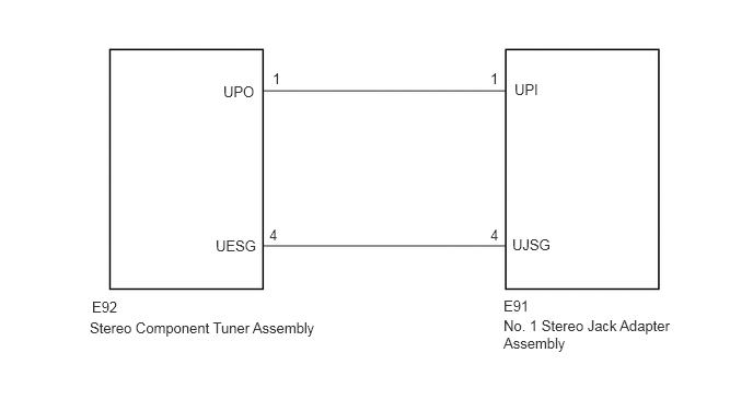
CAUTION / NOTICE / HINT
- HINT:
-
USB device or "iPod" may not be able to charge on vehicle when its battery is particularly depleted.
PROCEDURE
Disconnect the USB device or "iPod" from the No. 1 stereo jack adapter assembly.
Turn the ignition switch off.
- HINT:
-
When this malfunction occurs, it is necessary to turn off the ignition switch to make it possible for the vehicle to recognize a new device when it is connected.
Turn the ignition switch to ACC.
Connect a known good USB device or "iPod" to the No. 1 stereo jack adapter assembly.
- OK:
USB device or "iPod" charges.
- Result:
Proceed to OK NG
OK
NG
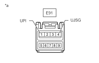
| *a | Front view of wire harness connector
(to No. 1 Stereo Jack Adapter Assembly) |
Disconnect the E91 No. 1 stereo jack adapter assembly connector.
Measure the voltage according to the value(s) in the table below.
- Standard Voltage:
Tester Connection Switch Condition Specified Condition E91-1 (UPI) - E91-4 (UJSG) Ignition switch ACC 5 V
- Result:
Proceed to OK NG
OK
NG
Disconnect the E92 No. 1 stereo component tuner assembly connector.
Disconnect the E91 stereo jack adapter assembly connector.
Measure the resistance according to the value(s) in the table below.
- Standard Resistance (Check for Open):
Tester Connection Condition Specified Condition E92-1 (UPO) - E91-1 (UPI) Always Below 1 Ω E92-4 (UESG) - E91-4 (UJSG) Always Below 1 Ω
- Standard Resistance (Check for Short):
Tester Connection Condition Specified Condition E92-1 (UPO) or E91-1 (UPI) - Body ground Always 10 kΩ or higher E92-4 (UESG) or E91-4 (UJSG) - Body ground Always 10 kΩ or higher
- Result:
Proceed to OK NG
OK
NG