RM19Y0E
_59
Vehicle Exterior
_003016
WINDOW / GLASS
_0015248
WINDOW DEFOGGER SYSTEM
U
WINDOW / GLASS WINDOW DEFOGGER SYSTEM TERMINALS OF ECU
MAIN BODY ECU (FUSE BLOCK ASSEMBLY)
a.
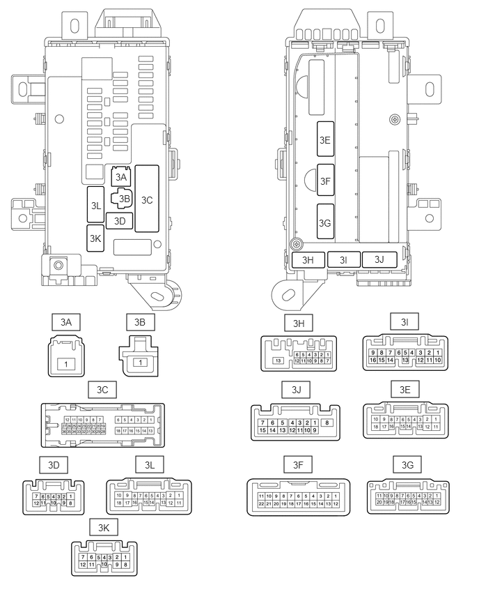
Disconnect the 3A and 3G main body ECU (fuse block assembly) connectors.
0.781,4.688 1.198,4.938
0.417,0.25
1.896,4.688 2.313,4.938
0.417,0.25
1.323,5.698 1.74,5.948
0.417,0.25
0.594,6.823 1.01,7.073
0.417,0.25
2.031,6.813 2.448,7.063
0.417,0.25
1.344,7.75 1.76,8
0.417,0.25
5.885,6.813 6.302,7.063
0.417,0.25
4.26,4.698 4.677,4.948
0.417,0.25
5.844,4.677 6.26,4.927
0.417,0.25
5.854,5.688 6.271,5.938
0.417,0.25
4.219,5.698 4.635,5.948
0.417,0.25
4.25,6.813 4.667,7.063
0.417,0.25
1.781,2.885 2.167,3.177
0.385,0.292
10
false
3B
2.115,2.906 2.51,3.208
0.396,0.302
10
false
3C
1.708,3.219 2.115,3.5
0.406,0.281
10
false
3D
4.781,2.01 5.25,2.333
0.469,0.323
10
false
3E
4.792,2.625 5.167,2.917
0.375,0.292
10
false
3F
4.771,3.25 5.25,3.583
0.479,0.333
10
false
3G
1.344,3.479 1.74,3.781
0.396,0.302
10
false
3K
1.365,2.99 1.76,3.292
0.396,0.302
10
false
3L
4.521,3.802 4.917,4.104
0.396,0.302
10
false
3H
5.083,3.802 5.479,4.104
0.396,0.302
10
false
3I
5.604,3.792 6.083,4.167
0.479,0.375
10
false
3J
1.729,2.563 2.083,2.833
0.354,0.271
10
false
3A
0.906,4.729 1.333,5
0.427,0.271
10
false
3A
2.01,4.729 2.396,5.021
0.385,0.292
10
false
3B
1.448,5.74 1.917,6.083
0.469,0.344
10
false
3C
0.719,6.865 1.125,7.146
0.406,0.281
10
false
3D
5.979,5.74 6.417,6.083
0.438,0.344
10
false
3E
4.385,6.865 4.802,7.188
0.417,0.323
10
false
3F
6.01,6.865 6.427,7.188
0.417,0.323
10
false
3G
4.385,4.75 4.781,5.052
0.396,0.302
10
false
3H
6,4.729 6.396,5.031
0.396,0.302
10
false
3I
4.365,5.74 4.76,6.042
0.396,0.302
10
false
3J
1.469,7.802 1.865,8.104
0.396,0.302
10
false
3K
2.167,6.865 2.563,7.167
0.396,0.302
10
false
3L
b.
Measure the voltage and resistance according to the value(s) in the table below.
| Terminal No. (Symbol) | Wiring Color | Terminal Description | Condition | Specified Condition |
|---|---|---|---|---|
| 3A-1 - Body ground | B - Body ground | Battery power supply | Always | 11 to 14 V |
| 3G-1 - Body ground | W-B - Body ground | Ground | Always | Below 1 Ω |
| 3G-11 - Body ground | W - Body ground | Ground | Always | Below 1 Ω |
| 3G-12 - Body ground | BR - Body ground | Ground | Always | Below 1 Ω |
If the result is not as specified, there may be a malfunction in the wire harness.
c.
Reconnect the 3A and 3G main body ECU (fuse block assembly) connectors.
d.
Measure the voltage according to the value(s) in the table below.
| Tester Connection | Wiring Color | Terminal Description | Condition | Specified Condition |
|---|---|---|---|---|
| 3C-6 - Body ground | B - Body ground | Ignition switch power supply | Ignition switch off | Below 1 V |
| Ignition switch ON | 11 to 14 V | |||
| 3H-1 - Body ground | V - Body ground | Ignition switch power supply | Ignition switch off | Below 1 V |
| Ignition switch ON | 11 to 14 V | |||
| 3L-17 - Body ground | B - Body ground | Rear window defogger signal output | Ignition switch ON, rear window defogger switch on | 11 to 14 V |
| 3J-1 - Body ground | P - Body ground | Rear window defogger switch assembly input | Ignition switch ON, rear window defogger switch on | Below 1 V |
| Ignition switch ON, rear window defogger switch off | 11 to 14 V | |||
| 3J-13 - Body ground | W - Body ground | window defogger indicator light output | Ignition switch ON, rear window defogger switch on | 11 to 14 V |
If the result is not as specified, the air conditioning amplifier assembly may have a malfunction.