RM19Y0E
_58
Vehicle Interior
_003008
METER / GAUGE / DISPLAY
_0015206
METER / GAUGE SYSTEM
U
METER / GAUGE / DISPLAY METER / GAUGE SYSTEM TERMINALS OF ECU
CHECK COMBINATION METER ASSEMBLY

3.458,0.188 3.875,0.427
0.417,0.24
3.531,0.229 4.115,0.594
0.583,0.365
10
E34
a.
Measure the resistance and voltage according to the value(s) in the table below.
| Terminal No. (Symbol) | Wiring Color | Terminal Description | Condition | Specified Condition |
|---|---|---|---|---|
| E34-3 (+B) - Body ground | P - Body ground | Battery power supply | Always | 11 to 14 V |
| E34-5 (IG) - Body ground | R - Body ground | Ignition switch power supply | Ignition switch off | Below 1 V |
| Ignition switch ON | 11 to 14 V | |||
| E34-7 (E) - Body ground | BR - Body ground | Ground | Always | below 1 Ω |
| E34-8 (CANL) - Body ground | P - Body ground | CAN communication signal | Ignition switch ON | Pulse generation |
| E34-9 (CANH) - Body ground | W - Body ground | CAN communication signal | Ignition switch ON | Pulse generation |
| E34-12 (T) - Body ground | SB - Body ground | DLC3 Communication | Always | 11 to 14 V |
| E34-14 (+) - Body ground | V - Body ground | Fuel sender gauge signal input | Fuel F (full tank) | Below 1 V |
| Fuel E (empty) | 4.5 to 9 V | |||
| E34-15 (PKB) - Body ground | GR - Body ground | Parking brake switch signal input | Ignition switch ON, parking brake switch off | 11 to 14 V |
| Ignition switch ON, parking brake switch on | Below 1 V | |||
| E34-19 (BTWG) - Body ground | R - Body ground | Front passenger side seat belt warning light signal output | Ignition switch ON, front passenger seat not occupied, or front passenger seat belt fastened | 11 to 14 V |
| Ignition switch ON, front passenger seat occupied, and front passenger seat belt unfastened | Pulse generation | |||
| E34-24 (+) - Body ground | LG - Body ground | LH side turn signal light signal input | Ignition switch ON, turn signal switch neutral position | Below 1 V |
| Ignition switch ON, turn signal switch turned to left | Alternating between below 1 and 11 to 14 V | |||
| E34-25 (+) - Body ground | BE - Body ground | RH side turn signal light signal input | Ignition switch ON, turn signal switch neutral position | Below 1 V |
| Ignition switch ON, turn signal switch turned to right | Alternating between below 1 and 11 to 14 V | |||
| E34-26 (SECR) - Body ground | Y - Body ground | Security indicator light signal input | Immobiliser system is unset | Below 1 V |
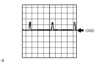
| Immobiliser system is set | Pulse generation
(See waveform 1) |
If the result is not as specified, the meter may have a malfunction.
b.
2.969,0.979 3.406,1.396
0.438,0.417
10
false
GND
Using an oscilloscope, check waveform 1.
| Item | Condition |
|---|---|
| Terminal No. (Symbol) | E34-26 (SECR) - Body ground |
| Tool setting | 5 V/DIV., 500 ms./DIV. |
| Condition | Immobiliser system is set |