HEATING / AIR CONDITIONING AIR CONDITIONING SYSTEM TERMINALS OF ECU
CHECK ECM
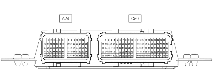
- HINT:
-
The standard voltage between each pair of the ECM terminals is shown in the table below. The appropriate conditions for checking each pair of the terminals are also indicated.
-
The result of checks should be compared with the standard voltage for that pair of terminals, and displayed in the "Specified Condition" column.
-
The illustration above can be used as a reference to identify the ECM terminal locations.
| Symbols (Terminal No.) | Wiring Color | Terminal Description | Condition | Specified Condition |
|---|---|---|---|---|
| A24-16 (MGC) - C50-4 (E01) | P - W-B | Magnetic clutch control signal | Ignition switch ON, magnetic clutch off | 11 to 14 V |
| Magnetic clutch on | Below 1.5 V | |||
| A24-29 (VCO) - A24-57 (E24) | Y - BR | Power source of air conditioner pressure sensor | Ignition switch ON | 4.75 to 5.25 V |
| A24-43 (ACAD) - A24-57 (E24) | B - BR | Air conditioner pressure sensor signal | Refrigerant pressure:
0 MPa (0 kgf/cm2, 0 psi) → 3.187 MPa (32.5 kgf/cm2, 462 psi)) |
0.5 to 4.8 V |
CHECK MAIN BODY ECU (FUSE BLOCK ASSEMBLY)
Disconnect the 3I main body ECU (fuse block assembly) connector.
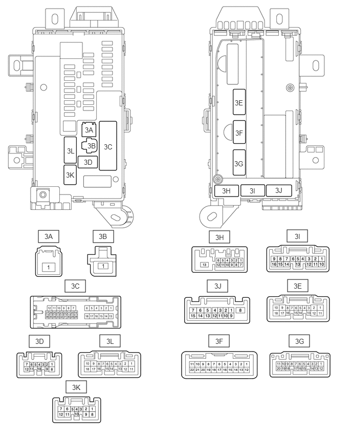
Measure the voltage and resistance according to the value(s) in the table below.
- HINT:
-
Measure the values on the wire harness side with the connectors disconnected.
| Tester Connection | Wiring Color | Terminal Description | Condition | Specified Condition |
|---|---|---|---|---|
| 3I-1 - Body ground | W-B - Body ground | Ground | Always | Below 1 Ω |
If the result is not as specified, there may be a malfunction in the wire harness.
Reconnect the 3I main body ECU (fuse block assembly) connector.
Measure the voltage according to the value(s) in the table below.
| Terminal No. | Wiring Color | Terminal Description | Condition | Specified Condition |
|---|---|---|---|---|
| 3B-1 - Body ground | W - Body ground | Battery power supply (for HTR relay) | Always | 11 to 14 V |
| 3D-4 - Body ground | V - Body ground | Ignition power supply (for No. 1 Integration relay) | Ignition switch OFF | Below 1 V |
| Ignition switch ON | 11 to 14 V | |||
| 3H-1 - Body ground | V - Body ground | Ignition power supply | Ignition switch OFF | Below 1 V |
| Ignition switch ON | 11 to 14 V | |||
| 3I-1 - Body ground | W-B - Body ground | Ground | Always | Below 1 V |
| 3J-2 - Body ground | R - Body ground | Blower motor | ·
Ignition switch ON ·
Blower switch ON |
Below 1 V |
·
Ignition switch ON ·
Blower switch OFF |
11 to 14 V | |||
| 3J-8 - Body ground | W - Body ground | Blower with fan motor sub-assembly power supply | Blower switch OFF | Below 1 V |
·
Ignition switch ON ·
Blower switch ON |
11 to 14 V | |||
| 3J-9 - Body ground | LG - Body ground | A/C switch | Ignition switch OFF | Below 1 V |
·
Ignition switch ON ·
A/C switch ON |
11 to 14 V | |||
| 3J-10 - Body ground | V - Body ground | No.1 cooler thermistor (A/C evaporator temperature sensor) | Air conditioner ON | 0.15 to 4.8 V |
| 3J-11 - Body ground | B - Body ground | A/C volume switch (Heater control assembly) | Ignition switch ON | Varies with volume |
| 3J-12 - Body ground | W-B - Body ground | Ground | Always | Below 1 V |
If the result is not as specified, the main body ECU (fuse block assembly) or instrument panel junction block assembly may be malfunctioning.