M5S MANUAL TRANSMISSION / TRANSAXLE OUTPUT SHAFT REASSEMBLY
PROCEDURE

 33321A
1.INSTALL OUTPUT SHAFT CENTER BEARING
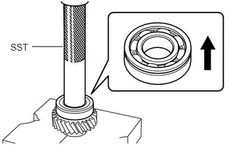
Using SST and a press, install a new output shaft center bearing to the output shaft.
- SST
- 09612-22011
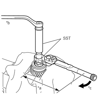
| *a | Torque Wrench Fulcrum Length |
| *b | Hold |
| *c | Turn |
Using SST, install a new output shaft center bearing lock nut.
- SST
- 09326-87501 09326-87502
- Torque:
- Specified tightening torque : 196 N*m (1999 kgf*cm, 145 ft.*lbf)
- NOTICE:
-
When installing the SST to the lock nut, securely tighten the hexagon part of the SST adjusting screw with a wrench and then tighten the lock nut.
- HINT:
- ·
Calculate the torque wrench reading when changing the fulcrum length of the torque wrench.
Click hereGeneral>INTRODUCTION>REPAIR INSTRUCTION>PRECAUTION
·When using SST (fulcrum length of 49 mm (1.93 in.)) + torque wrench (fulcrum length of 600 mm (23.6 in.)):
181 N*m (1846 kgf*cm, 133 ft.*lbf)
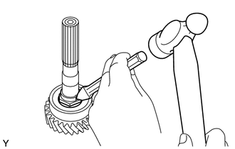
Using a chisel and a hammer, stake the output shaft center bearing lock nut.
33489
2.INSTALL SPEED SENSOR ROTOR
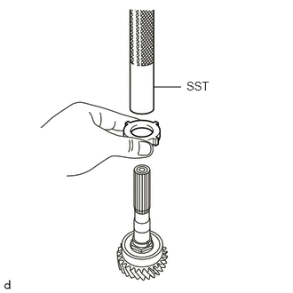
Using SST and a press, install the speed sensor rotor to the output shaft.
- SST
- 09612-22011
33321N
3.INSTALL RADIAL BALL BEARING
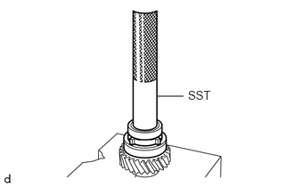
Using SST and a press, install a new radial ball bearing.
- SST
- 09612-22011
33367
4.INSTALL NO. 1 SYNCHRONIZER RING
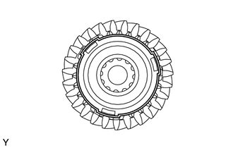
Install the No. 1 synchronizer ring to the output shaft.
Install the wave spring to the No. 1 synchronizer ring.
33311D
5.INSTALL INPUT SHAFT BEARING
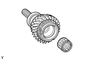
Coat the input shaft bearing with MP grease.
Install the input shaft bearing to the output shaft.