M5S MANUAL TRANSMISSION / TRANSAXLE COUNTER GEAR REASSEMBLY
PROCEDURE

 33360
1.INSTALL NO. 1 SYNCHRONIZER HUB ASSEMBLY
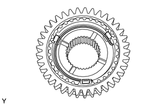
Coat the No. 1 hub sleeve with manual transmission gear oil, and install it to the No. 1 clutch hub.
Install the 3 synchromesh shifting keys and 2 synchromesh shifting key springs.
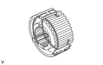
Make sure that the openings of the right and left synchromesh shifting key springs are not aligned.
33321V
2.INSTALL OUTPUT SHAFT CENTER BEARING
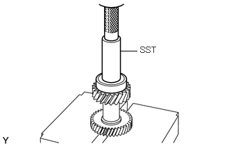
Using SST and a press, install a new output shaft center bearing.
- SST
- 09517-12011
33332
3.INSTALL 2ND GEAR
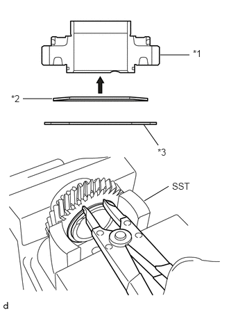
| *1 | 2nd Gear |
| *2 | Conical Spring Washer |
| *3 | 2nd Sub-gear |
Using SST, a vise and a snap ring expander, install the conical spring washer, 2nd sub-gear and snap ring to the 2nd gear.
- SST
- 09350-32014 (09351-32070)
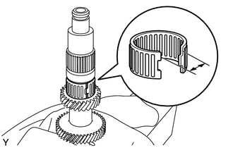
Coat the split type needle roller bearing with manual transmission gear oil, and install it to the counter gear shaft.
- NOTICE:
-
Do not widen the opening of the split type needle roller bearing 36 mm (1.42 in.) or more.
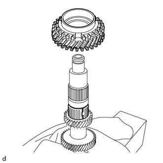
Install the 2nd gear.
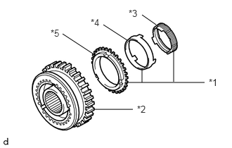
| *1 | No. 2 Synchronizer Ring Set |
| *2 | No. 1 Synchronizer Hub Assembly |
| *3 | Inner Ring |
| *4 | Middle Ring |
| *5 | Outer Ring |
Install the No. 2 synchronizer ring set to the No. 1 synchronizer hub assembly as follows.
- NOTICE:
-
Pay attention to the proper position.
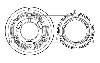
Fit the claws (A) of the inner ring into the holes (A') of the No. 1 synchronizer hub assembly.
Fit the synchromesh shifting keys (B') into the grooves (B) of the outer ring.
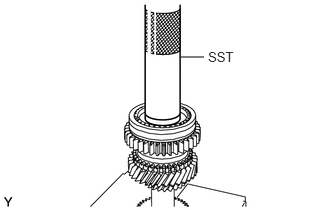
Using SST and a press, install the No. 1 synchronizer hub assembly and No. 2 synchronizer ring set.
- SST
- 09608-06041
- NOTICE:
-
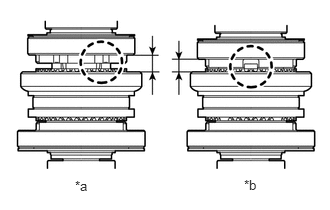 0.781,1.854 1.094,2.052 0.313,0.198 10 false *a 2.542,1.844 2.854,2.042 0.313,0.198 10 false *b
*a Incorrect *b Correct
-
Pay attention to the proper position. Fit the claws of the middle ring into the grooves of the 2nd gear.
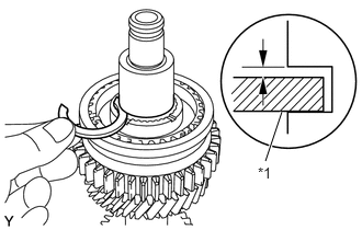
| *1 | Snap Ring |
Select a snap ring that allows the minimum amount of axial play.
- Standard clearance:
0 mm (0 in.)
- Maximum clearance:
0.16 mm (0.0063 in.)
| Part No. | Thickness mm (in.) | Part No. | Thickness mm (in.) |
|---|---|---|---|
| 9004A-52071 | 2.06 (0.0811) | 9004A-52075 | 1.90 (0.0748) |
| 9004A-52072 | 2.02 (0.0795) | 9004A-52076 | 1.86 (0.0732) |
| 9004A-52073 | 1.98 (0.0780) | 9004A-52077 | 1.82 (0.0717) |
| 9004A-52074 | 1.94 (0.0764) | 9004A-52078 | 2.10 (0.0827) |
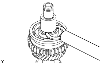
Using a brass bar and a hammer, install the snap ring to the input shaft.
33335
4.INSTALL 1ST GEAR
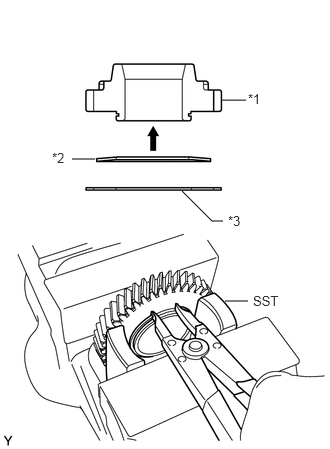
| *1 | 1st Gear |
| *2 | Conical Spring Washer |
| *3 | 1st Sub-gear |
Using SST, a vise and a snap ring expander, install the conical spring washer, 1st sub-gear and snap ring to the 1st gear.
- SST
- 09350-32014 (09351-32070)
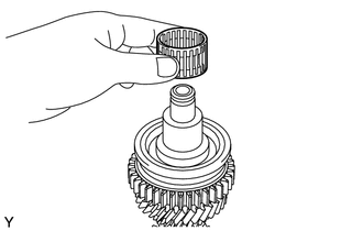
Coat the needle roller bearing with manual transmission gear oil, and install it to the counter gear shaft.
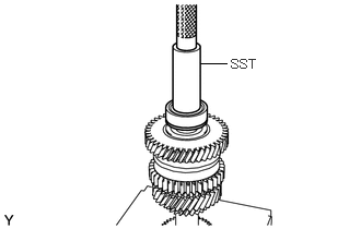
Using SST and press, install a new radial ball bearing, 1st gear thrust washer, 1st gear and No. 2 synchronizer ring.
- NOTICE:
-
Paying attention to the proper position, fit the synchromesh shifting key into the groove of the synchronizer ring.
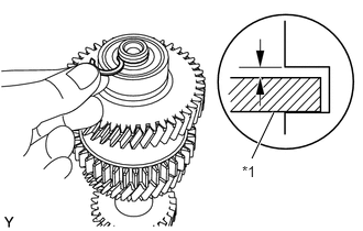
| *1 | Snap Ring |
Select a snap ring that allows the minimum amount of axial play.
- Standard clearance:
0 mm (0 in.)
- Maximum clearance:
0.16 mm (0.0063 in.)
| Part No. | Thickness mm (in.) | Part No. | Thickness mm (in.) |
|---|---|---|---|
| 9004A-52087 | 2.06 (0.0811) | 9004A-52091 | 1.90 (0.0748) |
| 9004A-52088 | 2.02 (0.0795) | 9004A-52092 | 1.86 (0.0732) |
| 9004A-52089 | 1.98 (0.0780) | 9004A-52093 | 1.82 (0.0717) |
| 9004A-52090 | 1.94 (0.0764) | 9004A-52094 | 1.78 (0.0701) |
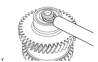
Using a brass bar and a hammer, install the snap ring to the counter gear shaft.