DRIVE SHAFT / PROPELLER SHAFT PROPELLER SHAFT ASSEMBLY ON-VEHICLE INSPECTION
PROCEDURE

 37110
1.INSPECT PROPELLER SHAFT ASSEMBLY
- HINT:
-
With the propeller shaft assembly installed to the vehicle, check the joint section of the propeller shaft for excessive play.
With both hands, forcefully move the joint spider in the direction of the A and B axes to check the joint section for play.
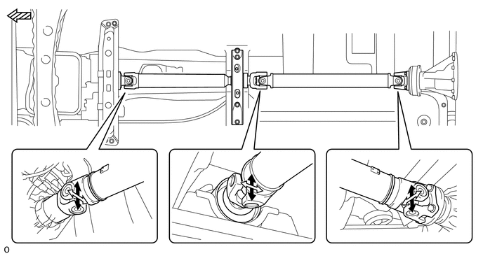

|
A-axis | 
|
B-axis |

|
Front of the Vehicle | - | - |
If the joint section has any play, measure it as follows. If the play exceeds the limit, replace the propeller shaft assembly with a new one.
Measurement of looseness in the A-axis direction
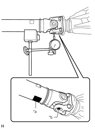
| *a | Magnetic Base Installation Point |
| *b | Measurement Point |
Set a dial gauge at the position shown in the illustration and vertically apply its gauge head to the bearing in the joint section.
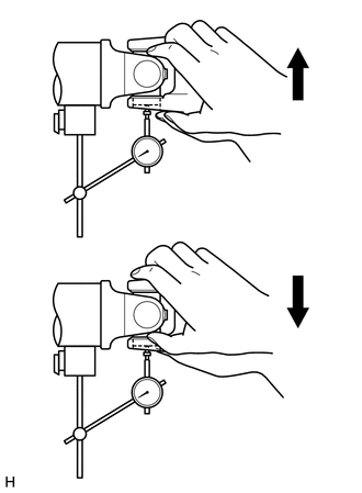
As the illustration shows, forcefully move the propeller shaft assembly up and down in the directions of the spider A-axis with both hands to measure the variation value with the gauge.
- Maximum bearing axial play:
0.2 mm (0.0079 in.)
- NOTICE:
-
Do not hold the propeller shaft tube during the measurement.
Measurement of looseness in the B-axis direction
Turn the propeller shaft assembly 90°.
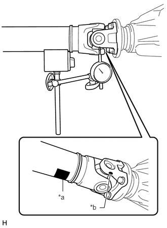
| *a | Magnetic Base Installation Point |
| *b | Measurement Point |
Set a dial gauge at the position shown in the illustration and vertically apply its gauge head to the universal joint flange yoke.
- NOTICE:
-
Ensure that the measurement point is correct.
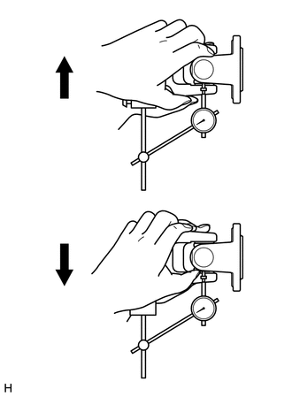
As the illustration shows, forcefully move the propeller shaft assembly up and down in the directions of the spider B-axis with both hands to measure the variation value with the gauge.
- Maximum bearing axial play:
0.2 mm (0.0079 in.)
- NOTICE:
-
Do not hold the propeller shaft tube during the measurement.