RM19Y0E
_58
Vehicle Interior
_003006
THEFT DETERRENT / KEYLESS ENTRY
_0015195
THEFT DETERRENT SYSTEM
J
THEFT DETERRENT / KEYLESS ENTRY THEFT DETERRENT SYSTEM Theft Warning ECU Communication Circuit
DESCRIPTION
The theft warning ECU assembly receives signals, such as intrusion sensor invalid signal, wireless operation answer-back signal, wireless lock/unlock operation signal, panic alarm operation signal and security buzzer output signal from the main body ECU (fuse block assembly). The theft warning ECU assembly transmits the hazard warning light signal to the main body ECU (fuse block assembly).
WIRING DIAGRAM
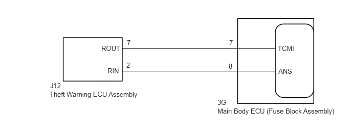
4.427,2.188 7.104,2.656
2.677,0.469
10
false
Main Body ECU (Fuse Block Assembly)
1.01,1.844 3.26,2.292
2.25,0.448
10
false
Theft Warning ECU Assembly
4.427,2.01 4.969,2.344
0.542,0.333
10
false
3G
1.021,1.667 1.563,2
0.542,0.333
10
false
J12
4.667,0.792 5.208,1.125
0.542,0.333
10
false
7
4.656,1.271 5.198,1.604
0.542,0.333
10
false
8
5.656,0.906 6.198,1.24
0.542,0.333
10
false
TCMI
5.667,1.375 6.208,1.708
0.542,0.333
10
false
ANS
2.583,0.792 3.125,1.125
0.542,0.333
10
false
7
2.573,1.25 3.115,1.583
0.542,0.333
10
false
2
2.063,0.906 2.698,1.229
0.635,0.323
10
false
ROUT
2.188,1.365 2.729,1.698
0.542,0.333
10
false
RIN
PROCEDURE
1.CHECK HARNESS AND CONNECTOR (THEFT WARNING ECU ASSEMBLY - MAIN BODY ECU (FUSE BLOCK ASSEMBLY))
a.
Disconnect the J12 theft warning ECU assembly connector.
b.
Disconnect the 3G main body ECU (fuse block assembly) connector.
c.
Measure the resistance according to the value(s) in the table below.
- Standard Resistance (Check for Open):
Tester Connection Condition Specified Condition J12-7 (ROUT) - 3G-7 Always Below 1 Ω J12-2 (RIN) - 3G-8 Always Below 1 Ω
- Standard Resistance (Check for Short):
Tester Connection Condition Specified Condition J12-7 (ROUT) or 3G-7 - Body ground Always 10 kΩ or higher J12-2 (RIN) or 3G-8 - Body ground Always 10 kΩ or higher
- Result:
Proceed to OK NG
OK
PROCEED TO NEXT INSPECTION PROCEDURE SHOWN IN PROBLEM SYMPTOMS TABLE
Click hereVehicle Interior>THEFT DETERRENT / KEYLESS ENTRY>THEFT DETERRENT SYSTEM>PROBLEM SYMPTOMS TABLE
NG
REPAIR OR REPLACE HARNESS OR CONNECTOR