RM19Y0E
_53
Suspension
_059025
TIRE PRESSURE MONITORING
_0288381
TIRE PRESSURE WARNING SYSTEM
J
TIRE PRESSURE MONITORING TIRE PRESSURE WARNING SYSTEM TC Terminal Circuit
DESCRIPTION
Tire pressure warning system DTCs can be checked by connecting terminals 13 (ECUT) and 4 (E) of the DLC3. The DTCs are indicated by blinking the tire pressure warning light.
WIRING DIAGRAM
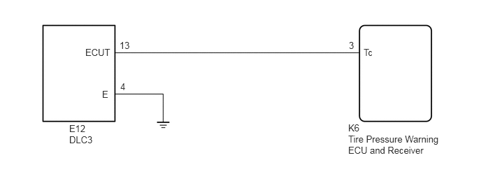
1.271,0.698 1.823,0.938
0.552,0.24
10
false
ECUT
1.521,1.323 1.833,1.521
0.313,0.198
10
false
E
1.781,0.594 2.094,0.792
0.313,0.198
10
false
13
1.792,1.208 2.104,1.406
0.313,0.198
10
false
4
1.031,1.833 1.344,2.031
0.313,0.198
10
false
E12
1.031,2 1.646,2.198
0.615,0.198
10
false
DLC3
5.188,1.823 5.635,2.021
0.448,0.198
10
false
K6
5.188,1.99 6.615,2.49
1.427,0.5
10
false
Tire Pressure Warning ECU and Receiver
5.417,0.698 5.729,0.896
0.313,0.198
10
false
Tc
5.198,0.594 5.51,0.792
0.313,0.198
10
false
3
PROCEDURE
1.CHECK HARNESS AND CONNECTOR (DLC3 - TIRE PRESSURE WARNING ECU AND RECEIVER AND BODY GROUND)
a.
Disconnect the tire pressure warning ECU and receiver K6 connector.
b.
Measure the resistance according to the value(s) in the table below.
- Standard Resistance:
Tester Connection Condition Specified Condition E12-13 (ECUT) - K6-3 (Tc) Always Below 1 Ω E12-13 (ECUT) or K6-3 (Tc) - Body ground Always 10 kΩ or higher E12-4 (E) - Body ground Always Below 1 Ω
- Result:
Proceed to OK NG
OK
CHECK PROCEED TO NEXT SUSPECTED AREA SHOWN IN PROBLEM SYMPTOMS TABLE
NG
REPAIR OR REPLACE HARNESS OR CONNECTOR OR EACH ECU