PARK ASSIST / MONITORING TOYOTA PARKING ASSIST-SENSOR SYSTEM CONTROL TOYOTA PARKING ASSIST-SENSOR CONTROL
FUNCTION OF MAIN COMPONENTS
| Component | Function | |
|---|---|---|
| Clearance Warning ECU Assembly | ·
Judges the approximate distance between the vehicle and an obstacle based on signals from the ultrasonic sensors. Output signals are sent to the multi-information display. ·
Sounds the No. 1 and No. 2 clearance warning buzzer. |
|
| Front Corner Ultrasonic Sensor (2) | Detects the distance between the vehicle and an obstacle. | |
| Front Center Ultrasonic Sensor (2) | ||
| Front Side Ultrasonic Sensor (2) | ||
| Rear Corner Ultrasonic Sensor (2) | ||
| Rear Center Ultrasonic Sensor (2) | ||
| Rear Side Ultrasonic Sensor (2) | ||
| Combination Meter Assembly | TOYOTA Parking Assist-sensor System Indicator Light | Illuminates to inform the driver when the system operation conditions are met. |
| Multi-information Display | ·
Displays the location of the obstacle and the approximate distance between the vehicle and the obstacle. ·
Displays an indication of a malfunction or freezing of an ultrasonic sensor to inform the driver. |
|
| Master Warning Light | Illuminates in accordance with the indication on the multi-information display. | |
| Combination Meter Assembly | Sends the TOYOTA parking assist-sensor system on/off signal to the clearance warning ECU assembly. | |
| No. 1 Clearance Warning Buzzer (Front) | Sounds to inform the driver according to the distance to the obstacle. | |
| No. 2 Clearance Warning Buzzer (Rear) | ||
| Steering Pad Switch Assembly | Sends operation signals from switches to the spiral cable with sensor sub-assembly. | |
| Spiral Cable with Sensor Sub-assembly | Sends operation signals from the steering pad switch assembly to the combination meter assembly. | |
| Steering Sensor | Sends the steering angle signal to the clearance warning ECU assembly. | |
| Shift Lever Position Sensor | Sends the shift position signals to the hybrid vehicle control ECU. | |
| Hybrid Vehicle Control ECU | Transmits the shift position signals to the clearance warning ECU assembly. | |
| Brake Booster with Master Cylinder Assembly
·
Skid Control ECU |
Sends the vehicle speed signal to the clearance warning ECU assembly. | |
| Airbag Sensor Assembly | Sends the G information signal to the clearance warning ECU assembly. | |
| Air Conditioning Amplifier Assembly | Sends outside temperature information to the clearance warning ECU assembly. | |
| Main Body ECU (Multiplex Network Body ECU) | ·
Sends model destination signal (information to indicate the market the vehicle was built for) to the clearance warning ECU assembly. ·
Sends the parking brake signal to the clearance warning ECU assembly. |
|
SYSTEM CONTROL
Detection Area
The detection areas of the ultrasonic sensor are as shown in the following illustration.
These detection areas are applicable when positioning a 60 mm (2.36 in.) diameter pole parallel or perpendicular to the ground. The ranges vary depending on the measuring method and type of obstacle.
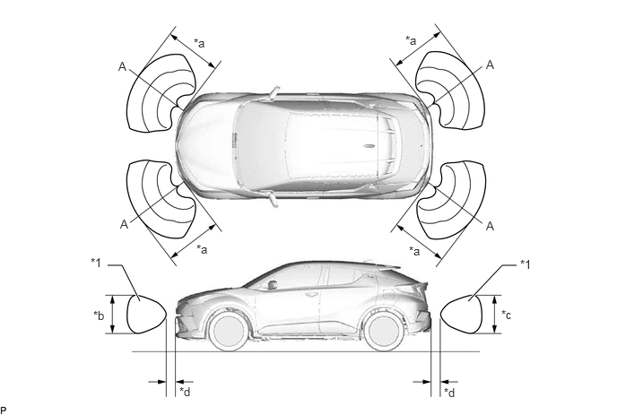
| *a | Approximately 500 mm (19.7 in.) | *b | Approximately 650 mm (25.6 in.) |
| *c | Approximately 550 mm (21.7 in.) | *d | Approximately 100 mm (3.9 in.) |
- NOTICE:
-
The ultrasonic sensor side view detection range area (labeled*1) represents the cross section of the top view of the lines of detection range A. The area*1 does not represent the entire side view detection range.
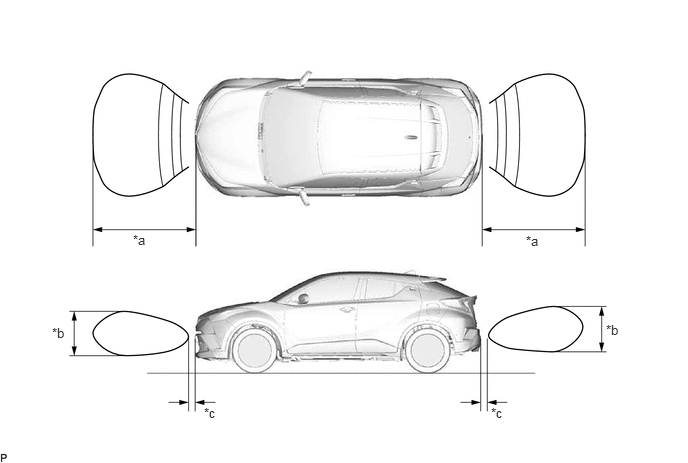
| *a | Approximately 1000 mm (39.4 in.) | *b | Approximately 650 mm (25.6 in.) |
| *c | Approximately 100 mm (3.9 in.) | - | - |
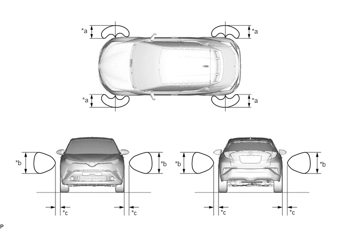
| *a | Approximately 1000 mm (39.4 in.) | *b | Approximately 400 mm (15.7 in.) |
| *c | Approximately 100 mm (3.9 in.) | - | - |
The operating condition of each sensor differs according to its installed position as shown in the table below:
| Installation Position | Operating Condition |
|---|---|
|
*: Even if the back sonar or clearance sonar switch assembly is off, the system is activated when the simple-intelligent parking assist system is operating. |
|
| Front Corner | ·
Power switch is ON. ·
System is activated.* ·
Shift lever is in a position other than P. ·
Vehicle speed is approximately 10 km/h (6 mph) or less. |
| Front Center | |
| Front Side | |
| Rear Side | |
| Rear Corner | ·
Power switch is ON. ·
System is activated.* ·
Shift lever is in R or has been shifted to N from R. |
| Rear Center | |
FUNCTION
TOYOTA Parking Assist-sensor System On/Off Setting
The TOYOTA parking assist-sensor system can be turned on or off via the setting screen displayed on the multi-information display.
The TOYOTA parking assist-sensor system indicator light is located in the combination meter assembly so that the driver can see whether the TOYOTA parking assist-sensor system is on. When the TOYOTA parking assist-sensor system is on, the TOYOTA parking assist-sensor system indicator light illuminates.
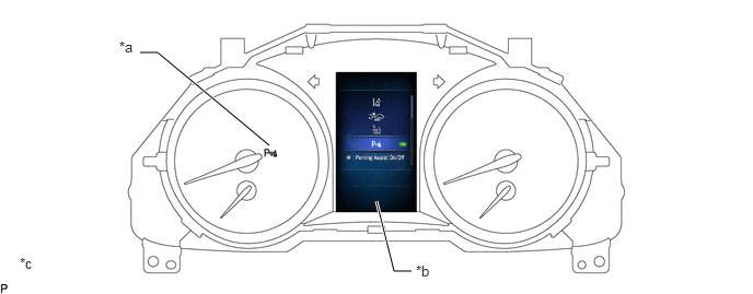
| *a | TOYOTA Parking Assist-sensor System Indicator Light | *b | Multi-information Display |
| *c | The illustration shown is an exampled only. The illustration may differ from the actual vehicle screen. | - | - |
Detection Area Scan Display
After turning the power switch ON, the scanned detection areas (gray) are displayed on the multi-information display.
The detection areas are displayed for 3 seconds after the scan by all ultrasonic sensors is completed.
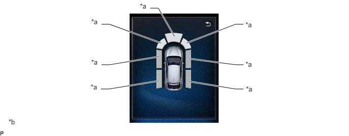
| *a | Scanned Detection Area | *b | The illustration shown is an example only. The illustration may differ from the actual vehicle screen. |
- HINT:
-
The side detection areas are scanned by the side ultrasonic sensors while the vehicle is moving.
DIAGNOSIS
If a system malfunction is detected, the clearance warning ECU assembly stores Diagnostic Trouble Codes (DTCs) in its memory. For details, refer to the Repair Manual.