NM32K0E
_57
Power Source / Network
_084579
M20A-FXS BATTERY / CHARGING
_0407539
CHARGING SYSTEM
DE
DETAILS
F
M20A-FXS BATTERY / CHARGING CHARGING SYSTEM DETAILS BATTERY SENSOR
CONSTRUCTION
a.
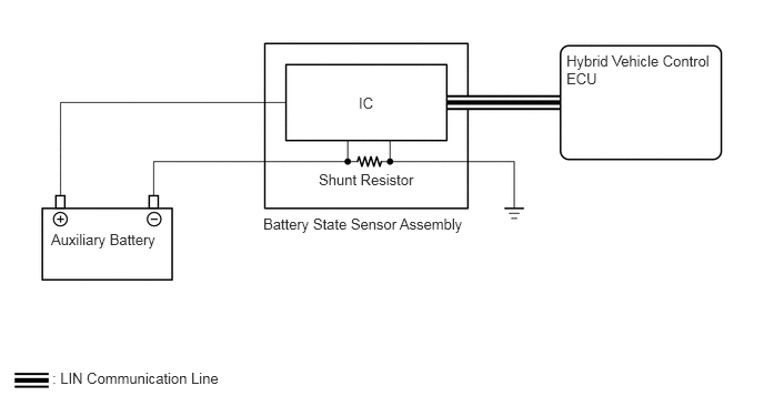
The battery state sensor assembly installed on the negative (-) auxiliary battery terminal calculates the current, voltage, battery temperature, SOC (battery charging percentage) and SOH (battery degradation percentage) and sends these signals to the hybrid vehicle control ECU via LIN communication.
b.
To detect the current, a shunt resistor installed inside the battery state sensor assembly is used to convert and calculate the voltage generated in the shunt resistor due to the auxiliary battery charge and discharge current.
c.
The auxiliary battery temperature is calculated from the resistance value of the thermistor built into the battery state sensor assembly.
0.479,2.167 1.802,2.417
1.323,0.25
10
false
Auxiliary Battery
0.49,3.469 2.115,3.667
1.625,0.198
10
false
: LIN Communication Line
3.365,0.885 3.635,1.083
0.271,0.198
10
false
IC
2.99,1.604 4.135,1.781
1.146,0.177
10
false
Shunt Resistor
2.469,2.021 4.531,2.302
2.063,0.281
10
false
Battery State Sensor Assembly
5.313,0.49 6.698,0.833
1.385,0.344
10
false
Hybrid Vehicle Control ECU