NM32K0E
_52
Drivetrain
_084636
P711 HYBRID TRANSMISSION / TRANSAXLE
_0407611
HYBRID TRANSAXLE SYSTEM
DE
DETAILS
F
P711 HYBRID TRANSMISSION / TRANSAXLE HYBRID TRANSAXLE SYSTEM DETAILS SHIFT LEVER
CONSTRUCTION
a.
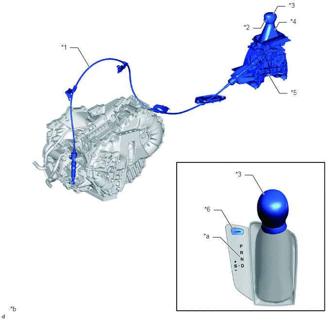
A straight type shift lever with boot that uses a transmission control cable assembly is used.
b.
The shift control mechanism consists of a shift lock control unit assembly, a shift lever knob sub-assembly and a transmission control cable assembly.
c.
A shift lock release button is provided inside the shift lever housing in consideration of emergency situations.
5.75,1.583 6,2
6,2 6.167,2
true
5.865,0.302 5.958,0.135
5.958,0.135 6.125,0.135
true
5.427,0.604 5.594,0.604
5.594,0.604 5.688,0.438
true
5.25,3.75 5.417,3.75
5.417,3.75 5.667,4.167
true
4.583,4.5 4.75,4.5
4.75,4.5 5,4.917
true
4.563,5.083 4.729,5.083
4.729,5.083 5.146,5.5
true
5.896,0.646 5.99,0.479
5.99,0.479 6.156,0.479
true
1.5,1.021 1.667,1.021
1.667,1.021 1.917,1.438
true
1.313,0.927 1.625,1.083
0.313,0.156
10
false
*1
5.229,0.5 5.542,0.656
0.313,0.156
10
false
*2
5.052,3.646 5.365,3.802
0.313,0.156
10
false
*3
6.229,0.375 6.542,0.531
0.313,0.156
10
false
*4
6.24,1.896 6.552,2.052
0.313,0.156
10
false
*5
4.385,4.396 4.698,4.552
0.313,0.156
10
false
*6
4.365,4.969 4.677,5.125
0.313,0.156
10
false
*a
0.219,6.531 0.531,6.688
0.313,0.156
10
false
*b
6.198,0.031 6.51,0.188
0.313,0.156
10
false
*3
| *1 | Transmission Control Cable Assembly | *2 | Shift Lever Knob Button |
| *3 | Shift Lever Knob Sub-assembly | *4 | Shift Boot |
| *5 | Shift Lock Control Unit Assembly | *6 | Shift Lock Release Button Cap |
| *a | Shift Pattern | *b | The illustrations shown are examples only. |
d.
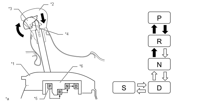
The shift lever used is a 5-position (P, R, N, D and S) straight type lever. Along with the change to a straight-type lever, a detent mechanism using shift lever knob button operation was added to prevent accidentally shifting from P to R, R to P, or N to R.
Detent Mechanism (Image)
1.365,1 2.115,1.25
2.115,1.25 2.281,1.25
true
0.5,0.333 0.667,0.333
0.667,0.333 1,0.75
true
1.417,0.375 1.583,0.167
1.583,0.167 1.75,0.167
true
0.583,2.333 0.75,2.333
0.75,2.333 1.083,2.75
true
1.427,3.594 1.594,3.594
1.594,3.594 1.771,3.198
true
2.167,3 2.635,2.417
2.635,2.417 2.802,2.417
true
0.396,2.229 0.708,2.385
0.313,0.156
10
false
*1
1.823,0.063 2.135,0.219
0.313,0.156
10
false
*2
0.302,0.229 0.615,0.385
0.313,0.156
10
false
*3
2.354,1.146 2.667,1.302
0.313,0.156
10
false
*4
1.229,3.49 1.542,3.646
0.313,0.156
10
false
*5
2.875,2.313 3.188,2.469
0.313,0.156
10
false
*6
0.198,3.5 0.51,3.656
0.313,0.156
10
false
*a
| *1 | Shift Lock Control Unit Assembly | *2 | Shift Lever Knob Sub-assembly |
| *3 | Shift Lever Knob Button | *4 | Detent Rod |
| *5 | Detent Plate | *6 | Detent |
| *a | The illustrations shown are examples only. | - | - |

|
Shift Lever knob button operation necessary | 
|
Shift Lever knob button operation not necessary |