NM32K0E
_52
Drivetrain
_084636
P711 HYBRID TRANSMISSION / TRANSAXLE
_0407612
SHIFT LOCK SYSTEM
GE
GENERAL
F
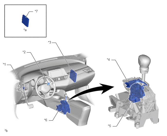
P711 HYBRID TRANSMISSION / TRANSAXLE SHIFT LOCK SYSTEM GENERAL PARTS LOCATION
2.229,1.833 2.396,1.833
2.396,1.833 3.063,3
true
0.292,2.781 0.458,2.781
0.458,2.781 1.01,3.74
true
1.146,2.25 1.313,2.25
1.313,2.25 2.063,3.563
true
2.094,5.167 2.26,5.167
2.26,5.167 2.51,4.75
true
4.833,5.417 5,5.417
5,5.417 5.667,4.333
true
4.781,2.573 4.948,2.573
4.948,2.573 5.5,3.531
true
1.104,0.75 1.25,0.5
1.25,0.5 1.417,0.5
true
0.125,2.677 0.438,2.833
0.313,0.156
10
false
*1
0.969,2.146 1.281,2.302
0.313,0.156
10
false
*2
2.063,1.729 2.375,1.885
0.313,0.156
10
false
*3
4.583,2.469 4.896,2.625
0.313,0.156
10
false
*4
4.635,5.313 4.948,5.469
0.313,0.156
10
false
*5
1.896,5.063 2.208,5.219
0.313,0.156
10
false
*6
1.49,0.396 1.802,0.552
0.313,0.156
10
false
*7
1.01,1.198 1.323,1.354
0.313,0.156
10
false
*a
0.198,5.521 0.51,5.677
0.313,0.156
10
false
*b
| *1 | Stop Light Switch Assembly | *2 | Power Switch (Push Start Switch) |
| *3 | Hybrid Vehicle Control ECU | *4 | Shift Lock Release Button |
| *5 | Shift Lock Solenoid Assembly
·
Shift Lock Control ECU ·
Shift Lock Solenoid ·
P Detection Switch |
*6 | Shift Lock Control Unit Assembly |
| *7 | Certification ECU (Smart Key ECU Assembly) | - | - |
| *a | Refer to Service Bulletin for the installation position of the parts. | *b | The illustrations shown are examples only. |