NM32K0E
_51
Engine / Hybrid System
_084637
M20A-FXS ENGINE CONTROL
_0407613
SFI SYSTEM
DE
DETAILS
F
M20A-FXS ENGINE CONTROL SFI SYSTEM DETAILS CAMSHAFT POSITION SENSOR
CONSTRUCTION
a.
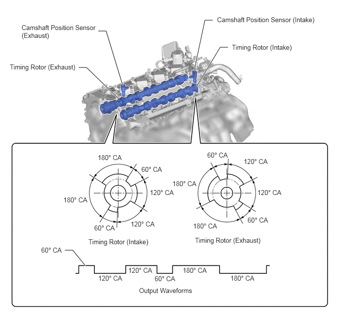
Magnetic Resistance Element (MRE) type camshaft position sensors (intake and exhaust) are used. To detect each camshaft position, a timing rotor that is secured to the camshaft is used to generate 3 pulses for every 2 revolutions of the crankshaft. The timing rotor for each camshaft is part of the respective camshaft.
2.604,1.813 2.25,0.656
2.25,0.656 2.083,0.656
true
2.521,2.094 1.833,1.427
1.833,1.427 1.667,1.427
true
4.115,1.5 4.344,0.427
4.344,0.427 4.51,0.427
true
4.167,1.833 4.667,1
4.667,1 4.833,1
true
1.813,5.625 1.542,5.292
1.542,5.292 1.375,5.292
true
0.458,0.5 2.083,0.896
1.625,0.396
10
false
Camshaft Position Sensor (Exhaust)
0.208,1.333 1.948,1.615
1.74,0.281
10
false
Timing Rotor (Exhaust)
4.604,0.333 6.938,0.625
2.333,0.292
10
false
Camshaft Position Sensor (Intake)
4.917,0.917 6.625,1.198
1.708,0.281
10
false
Timing Rotor (Intake)
2.073,3.25 2.75,3.5
0.677,0.25
10
false
180° CA
1.344,4.146 2.021,4.396
0.677,0.25
10
false
180° CA
4.094,4.698 4.771,4.948
0.677,0.25
10
false
180° CA
3.656,3.802 4.333,4.052
0.677,0.25
10
false
180° CA
3,3.5 3.677,3.75
0.677,0.25
10
false
60° CA
5.25,4.573 5.927,4.823
0.677,0.25
10
false
60° CA
4.396,3.198 5.073,3.448
0.677,0.25
10
false
60° CA
5.167,3.333 5.844,3.583
0.677,0.25
10
false
120° CA
5.458,3.99 6.135,4.24
0.677,0.25
10
false
120° CA
3.177,3.99 3.854,4.24
0.677,0.25
10
false
120° CA
2.771,4.656 3.448,4.906
0.677,0.25
10
false
120° CA
1.875,5.031 3.583,5.313
1.708,0.281
10
false
Timing Rotor (Intake)
4.135,5 5.844,5.281
1.708,0.281
10
false
Timing Rotor (Exhaust)
2,4.74 2.677,4.99
0.677,0.25
10
false
60° CA
2.083,5.802 2.76,6.052
0.677,0.25
10
false
120° CA
2.719,5.635 3.396,5.885
0.677,0.25
10
false
120° CA
3.875,5.635 4.552,5.885
0.677,0.25
10
false
180° CA
4.885,5.802 5.563,6.052
0.677,0.25
10
false
180° CA
3.281,5.813 3.958,6.063
0.677,0.25
10
false
60° CA
0.875,5.208 1.552,5.458
0.677,0.25
10
false
60° CA
2.948,6.063 4.656,6.344
1.708,0.281
10
false
Output Waveforms
b.
An MRE type camshaft position sensor consists of an MRE, a magnet and a sensor. The direction of the magnetic field changes due to the profile (protruding and non-protruding portions) of the timing rotor, which passes by the sensor. As a result, the resistance of the MRE changes, and the output voltage to the ECM changes to high or low. The ECM detects the camshaft position based on this output voltage.