NAVIGATION / MULTI INFO DISPLAY NAVIGATION SYSTEM(for Single Knob Type) CONTROL AUDIO AND VISUAL CONTROL
FUNCTION OF MAIN COMPONENTS
| Component | Function | |
|---|---|---|
| Audio Head Unit | Radio and Display Receiver Assembly | ·
Displays the USB video screen, each type of audio operation information, etc. ·
Outputs the audio signal of the selected audio source to the stereo component amplifier assembly. |
| Speakers | Output the audio sounds. | |
| Stereo Component Amplifier Assembly*1 | Amplifies audio signals sent from the audio head unit. | |
| Rear Spoiler sub-assembly (Radio Antenna)
·
FM Main |
Receives radio broadcasting signals. (FM Main) | |
| Window Glass Antenna Wire
·
FM Sub ·
DAB*2 |
·
Receives radio broadcasting signals. (FM Sub) ·
Receives digital audio broadcasts via the back door glass antenna printed antenna array. (DAB)*2 |
|
| No. 1 Amplifier Antenna Assembly | Amplifies radio broadcasting signals from the radio antenna and sends them to the audio head unit. | |
| Digital Audio Broadcasting Antenna Assembly*2 | Amplifies digital audio broadcasts signals from the DAB antenna and sends them to the audio head unit. | |
| Navigation Antenna Assembly | Telephone Antenna | Receives signals from the application server. |
| GPS Antenna | Receives signals from GPS satellites and transmits these signals to the audio head unit. | |
| Steering Pad Switch Assembly | Sends operation signals such as volume adjustment, mode selection and song selections to the audio head unit. | |
| Telephone Microphone Assembly | ·
Detects voice during hands-free conversations and voice commands. ·
Is installed in the roof headlining and converts sound waves to an electrical signal and sends it to the audio head unit. |
|
| No. 1 Stereo Jack Adapter Assembly | When a USB memory device, portable audio player (USB type) or Apple device is connected, communicates with the audio head unit via USB. | |
| Combination Meter Assembly | ·
Displays various information and operation signals on the multi-information display sent from the audio head unit via local bus communication. ·
Sends the vehicle speed signal to the audio head unit and stereo component amplifier assembly. |
|
| DCM (Telematics Transceiver)*3 | ·
When using the Wi-Fi hotspot, sends and receives mobile phone band frequency data. ·
Transmits and receives data from the data center. |
|
*1: Models with 9-speaker sound system
*2: Models with DAB Function
*3: Models with DCM (Telematics Transceiver)
FUNCTION
Automatic Sound Levelizer (ASL)
The Automatic Sound Levelizer (ASL) function automatically adjusts the audio system volume level in order to compensate for increased vehicle noise (vehicle noise tends to increase as vehicle speed increases).
Vehicle speed signals are received from the combination meter assembly and used for ASL control.
Audio Head Unit Supply Power
The start and stop method of the audio and visual system can be set by setting the ACC customize item to ON/OFF on the settings screen.
When the value is set to "ON", the audio and visual system starts when the ignition switch is turned to ON (ACC) or ON (IG), and stops when the ignition switch is turned off.
With the value set to "OFF", the audio head unit is energized by supply power (+BA) when an occupant enters the vehicle and the system performs startup processing in the background. Accordingly, even though the ignition switch is off, the audio and visual system can start quickly when a start operation is performed (audio head unit power switch ON operation is performed or the ignition switch is turned to ON (IG)). Furthermore, the audio and visual system can be set to continue in the ON state even after the ignition switch is turned from ON (IG) to off. Supply power (+BA) to the audio head unit used when an occupant enters the vehicle can be shut down when the audio and visual system is turned off by turning off the audio head unit or by opening the driver door with the ignition switch off.
If the hybrid system is stopped and the audio and visual system continues for an extended amount of time, the supply power to the audio head unit is automatically cut off in accordance with the supply power management when the vehicle is stopped.
- HINT:
-
When the value of the setting is set to "OFF", the ignition switch cannot be turned to ON (ACC) or turned off. By turning the power switch of the audio head unit ON or OFF, the ACC supply power can be energized or de-energized.
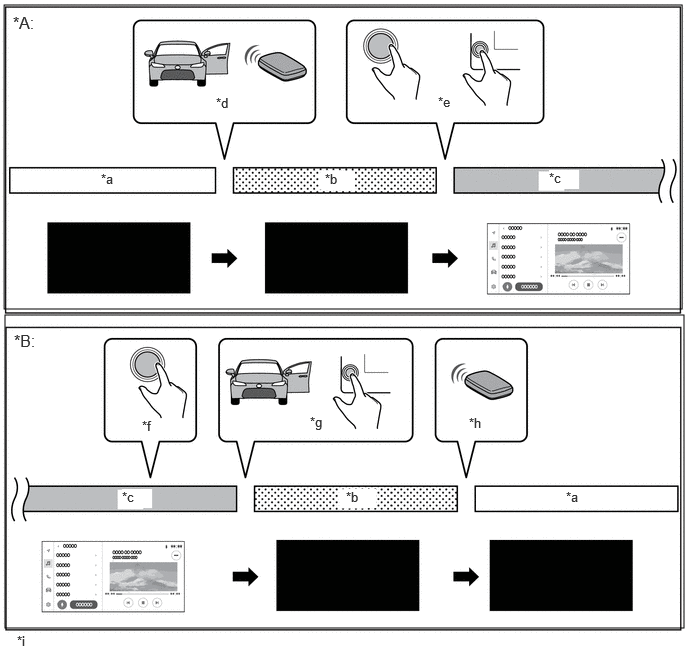
| *A | Operation when entering vehicle | *B | Operation when exiting vehicle |
| *a | Supply power (+BA) off
(audio and visual system off) |
*b | Supply power (+BA) on
(audio and visual system off) |
| *c | Audio head unit power on
(audio and visual system on) |
*d | Driver door opened and closed after door unlock operation |
| *e | Ignition switch turned to ON (IG) or power switch of audio head unit set to ON | *f | Ignition switch turned off |
| *g | Driver door opened or power switch of audio head unit set to OFF | *h | Door lock operation |
| *i | This image is an example. | - | - |
Driver Profile Control
When verification is performed via a "Bluetooth" device*1, the audio and visual system can be used using the settings content (driver profile) stored for each driver profile*2.*3
For each driver profile, the settings of each function such as the driver profile name, "Bluetooth", "Wi-Fi", etc., can be saved.*4
Driver profile registration, setting driver identification device settings, changing the driver profile, initializing a driver profile, etc., can be performed using the multi-display.
The audio and visual system related settings information inside each driver profile is uploaded to a dedicated server via DCM communication. Uploaded settings information can be downloaded to another vehicle.*5
- HINT:
*1: It is necessary to register a mobile device that is compatible with SPP (Serial Port Profile) Ver. 1.2 or higher to the audio head unit.
*2: The maximum number of driver profiles that can be registered to the audio head unit is 3.
*3: In order to use the driver profile, it is necessary to have a valid dedicated account. When not using a driver profile, the vehicle can be used with a guest profile.
*4: The values that can be set may vary depending on the vehicle specifications.
*5: Applicable only in areas where access to the dedicated server is possible. In areas where access to the dedicated server is not possible, it is necessary to register the driver profile of each vehicle separately.
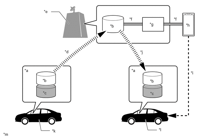
| *a | Driver Profile | *b | Audio and Visual System Settings Information |
| *c | Settings Information Linked to In-vehicle Device | *d | Upload via DCM Communication |
| *e | Dedicated Server | *f | Management via Account Information of Dedicated Smartphone Application |
| *g | Account Information of Dedicated Smartphone Application | *h | Dedicated Smartphone Application |
| *i | Registration/Addition of Driver Profile via Account of Dedicated Smartphone Application | *j | Download via DCM Communication |
| *k | Vehicle of User | *l | Other Vehicle Such as Rental Vehicle |
| *m | This image is an example. | - | - |
Security Lock Control
The first time the system is started after the battery is removed from the vehicle, the security lock screen is displayed and the audio and visual system stops.
By entering the cancel password on the security lock screen, the security lock screen will be canceled.
Security lock screen control can be set ON/OFF and the cancel password can be set using the setting mode screen.
- NOTICE:
-
If the password is incorrectly entered on the security lock screen 20 times, the password can no longer be entered. In this case, it is necessary to perform a screen unlock using the service tool. For details, refer to the Repair Manual.
Privacy Mode (for Europe)
By using privacy mode, the user can stop their position information* from being sent to services outside the vehicle depending on the preferences of the user.
- HINT:
- ·
*: Position information is information that can directly identify a position such as a home address, destination, latitude and longitude, etc., or indirectly identify a position in conjunction with other data such as photos taken at the destination or outside of the vehicle.
·When transmission of position information is disabled, uploading of information for some functions will be limited.
Software Update Function
The software update function will be available when a delivery of a new software starts.
The software update function is an easy to use convenient function that automatically checks the new software update schedule, sends update information, confirms the contents of the update, displays a progress bar indicating the installation status, enables software update history to be checked, etc.
The update data can be acquired via DCM communication*, "Wi-Fi" communication* or USB storage device.
- HINT:
-
*: Depending on the destination, the software update via DCM communication or "Wi-Fi" communication may not be possible.
The following contents will be delivered using the software update function.
| Item | Details |
|---|---|
| Action | Software push regarding recall, remediation measures, service campaign, etc. |
| Function/performance improvement | Software push with the goal of improved functions/performance such as correction of system malfunctions. |
| Marketability maintenance | Software push with the goal of maintained marketability such as connection compatibility with external devices, improvements to the screen display, etc. |
| Marketability improvement | Software push with the goal of improved marketability such as the addition of new functions. |
The software update is performed mainly using the following methods.
| Method | Details |
|---|---|
| Manual update by user | By checking the audio head unit for a software update, a manual update is performed. |
| Update notification during power on operation | When power is supplied to the audio head unit, new software update information is displayed on the multi-display. |
| Update notification via push server* | Whenever the push server pushes the update, new software update information is displayed on the multi-display. |
| Manual update via USB storage device | A manual update is performed using update data saved to a USB storage device. |
- NOTICE:
- ·
When performing a software update via a USB storage device, it may take a long amount of time to verify the USB storage device if there are many unrelated files stored on the device when performing the update.
·After performing the update, it is not possible to revert to the previous version.
·It is necessary for the customer to incur the cost of the USB storage device, all computer communication fees, etc.
- HINT:
- ·
When performing the software update function, the contents of each function of the audio and visual system may change.
·*: Depending on the destination, the update notification from the push server may not be possible.
Delivery Application Function (Models with Delivery Application Function)
By using the delivery application function, the addition and update of services is possible via an application installed to the audio head unit from the data center.
The delivery application can be linked with each ECU and the multimedia function of the audio head unit, and can communicate with external servers.
By utilizing applications obtained from the application market provided by data center various applications can be managed.
- HINT:
- ·
It is necessary to enter a telematics service contract and subscription service contract to use the delivery application function.
·The availability of applications from the application market may vary by region.
Navigation Function*1
The navigation function performs route guidance using the navigation system built into the audio head unit.
By accessing the data center, the latest map database of the data center can be used by the navigation function. The route search using the map database of the data center will offer optimal routes in accordance with traffic information, such as traffic jams, etc.*2*3
Even when it is not possible to access the data center due to deterioration of the vehicle communication environment, the navigation function performs route guidance using the navigation system built into the audio head unit. When the vehicle communication environment returns to normal, the navigation system automatically accesses the data center and uses the latest map database for optimal route guidance.
- HINT:
-
*1: Refer to the owner's manual for details of navigation function.
-
*2: A subscription service may be necessary to search for an optimal route using the map database of the data center.
-
*3: Depending on the destination, it may not be possible to use a function of the map database of the data center.
DIAGNOSIS
For details on the procedure required to enter the Service Menu screen, refer to the Repair Manual.