2ZR-FXE EMISSION CONTROL EGR COOLER INSTALLATION
PROCEDURE

 25601L
1.INSTALL EGR PIPE WITH COOLER SUB-ASSEMBLY
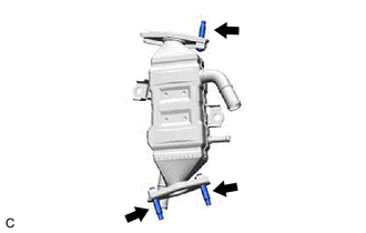
Using an E8 "TORX" socket wrench, install the 3 stud bolts to the EGR pipe with cooler sub-assembly.
- HINT:
-
If a stud bolt is deformed or the threads are damaged, replace it.
- Torque:
- 5.0 N*m (51 kgf*cm, 44 in.*lbf)
Install a new EGR valve gasket to the EGR valve assembly.
Install the EGR pipe with cooler sub-assembly to the EGR valve assembly with the 2 nuts.
- Torque:
- 21 N*m (214 kgf*cm, 15 ft.*lbf)
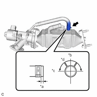
| *a | 0 to 4 mm (0 to 0.157 in.) |
| *b | Left Side of Vehicle |
| *c | Front Side of Vehicle |
| *d | 180° |
Connect the No. 6 water by-pass hose to the EGR pipe with cooler sub-assembly and slide the clip to secure it.
Install a new EGR cooler gasket to the EGR pipe with cooler sub-assembly.
Set the EGR pipe with cooler sub-assembly with the EGR valve assembly to the engine assembly.
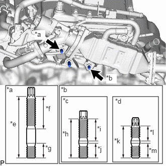
| *a | Stud Bolt (A) |
| *b | Stud Bolt (B) |
| *c | Type A |
| *d | Type B |
| *e | 48 mm (1.890 in.) |
| *f | 26 mm (1.024 in.) |
| *g | 13 mm (0.512 in.) |
| *h | 35 mm (1.377 in.) |
| *i | 20 mm (0.787 in.) |
| *j | 13 mm (0.512 in.) |
| *k | 29 mm (1.142 in.) |
| *l | 14 mm (0.551 in.) |
| *m | 13 mm (0.512 in.) |
Using an E8 "TORX" socket wrench, install the stud bolt (A) and stud bolt (B) to the cylinder head sub-assembly and camshaft housing sub-assembly.
- HINT:
-
If a stud bolt is deformed or the threads are damaged, replace it.
- Torque:
- 9.5 N*m (97 kgf*cm, 84 in.*lbf)
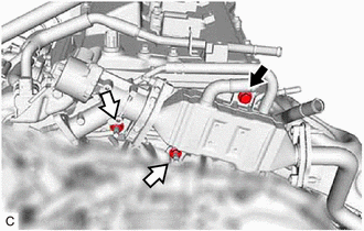

|
Bolt |

|
Nut |
Temporarily install the EGR pipe with cooler sub-assembly with the EGR valve assembly to the cylinder head sub-assembly and camshaft housing sub-assembly with the bolt and 2 nuts.
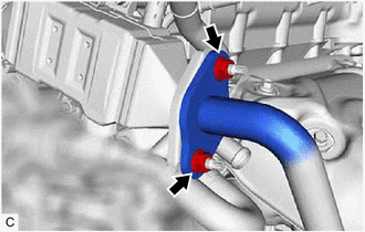
Temporarily install the EGR pipe with cooler sub-assembly to the exhaust manifold (TWC: Front Catalyst) with 2 new nuts.
Tighten the bolt and 2 nuts.
- Torque:
- 21 N*m (214 kgf*cm, 15 ft.*lbf)
Tighten the 2 nuts.
- Torque:
- 26 N*m (265 kgf*cm, 19 ft.*lbf)
Connect the EGR valve assembly connector.
16281
2.CONNECT NO. 4 WATER BY-PASS HOSE
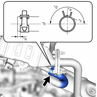
| *a | Top of Vehicle |
| *b | Left Side of Vehicle |
| *c | Paint Mark |
| *d | 180° |
| *e | 0 to 4 mm (0 to 0.157 in.) |
Connect the No. 4 water by-pass hose to the EGR pipe with cooler sub-assembly and slide the clip to secure it.
- HINT:
-
Engage the clip within the area shown in the illustration.
87245A
3.CONNECT INLET HEATER WATER HOSE A
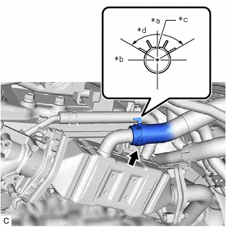
| *a | Top of Vehicle |
| *b | Left Side of Vehicle |
| *c | Paint Mark |
| *d | 120° |
Connect the inlet heater water hose A to the EGR pipe with cooler sub-assembly and slide the clip to secure it.
- HINT:
-
Engage the clip within the area shown in the illustration.
16261
4.CONNECT WATER BY-PASS HOSE
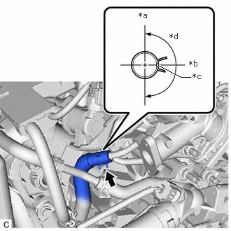
| *a | Top of Vehicle |
| *b | Left Side of Vehicle |
| *c | Paint Mark |
| *d | 180° |
Connect the water by-pass hose to the EGR valve assembly and slide the clip to secure it.
- HINT:
-
Engage the clip within the area shown in the illustration.
25610
5.INSTALL EGR PIPE ASSEMBLY
16671
6.INSTALL FLOW SHUTTING VALVE (WATER VALVE)
7.INSPECT FOR EXHAUST GAS LEAK
If gas is leaking, tighten the areas necessary to stop the leak. Replace damaged parts as necessary.
- HINT:
-
Perform Inspection After Repair after repairing an exhaust gas leak.
-
Click hereEngine / Hybrid System>2ZR-FXE (ENGINE CONTROL)>SFI SYSTEM>INITIALIZATION