Home › Power Source / Network › POWER DISTRIBUTION › INTEGRATION RELAY
RM32K0E _57 Power Source / Network _061291 POWER DISTRIBUTION _0299565 INTEGRATION RELAY G

POWER DISTRIBUTION  INTEGRATION RELAY  INSPECTION  


PROCEDURE

Hide 82641 1.INSPECT NO. 1 INTEGRATION RELAY
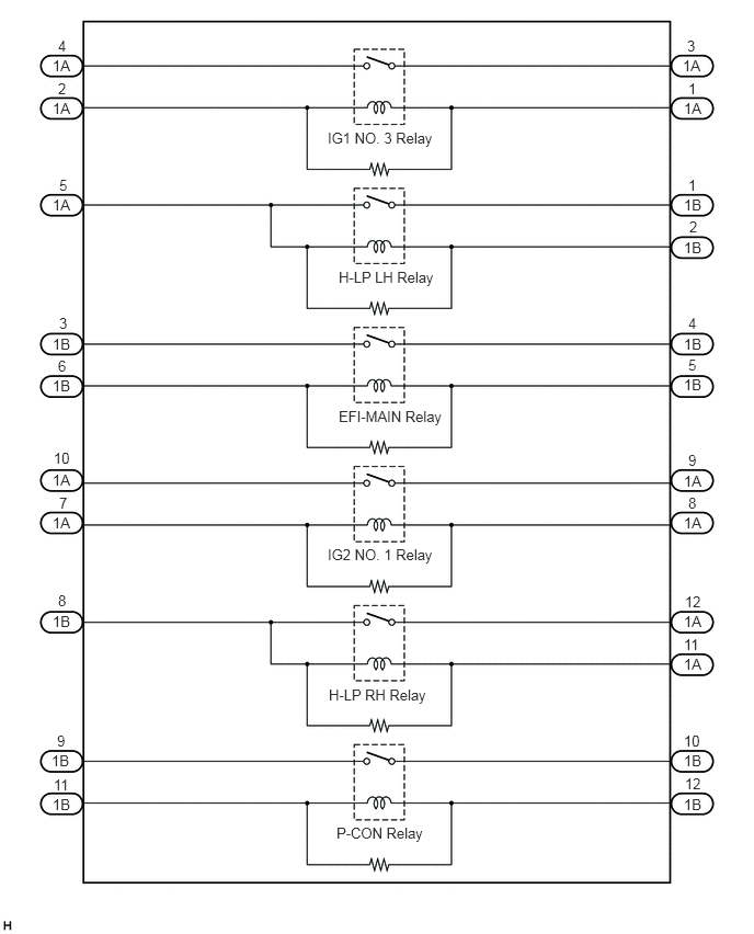
E340362E04
3.115,1.229 4.521,1.427 1.406,0.198 10 false IG1 NO. 3 Relay 3.219,2.552 4.188,2.74 0.969,0.188 10 false H-LP LH Relay 3.219,3.875 4.229,4.042 1.01,0.167 10 false EFI-MAIN Relay 3.115,5.188 4.281,5.365 1.167,0.177 10 false IG2 NO. 1 Relay 3.125,6.521 4.198,6.698 1.073,0.177 10 false H-LP RH Relay 3.198,7.833 4.146,8 0.948,0.167 10 false P-CON Relay 0.5,7.563 0.75,7.719 0.25,0.156 10 false 1B 0.49,7.146 0.74,7.302 0.25,0.156 10 false 1B 0.5,5.823 0.75,5.979 0.25,0.156 10 false 1B 0.5,4.885 0.75,5.042 0.25,0.156 10 false 1A 0.5,4.479 0.75,4.635 0.25,0.156 10 false 1A 0.5,3.188 0.75,3.344 0.25,0.156 10 false 1B 0.5,3.583 0.75,3.74 0.25,0.156 10 false 1B 0.5,1.865 0.75,2.021 0.25,0.156 10 false 1A 0.5,0.948 0.75,1.104 0.25,0.156 10 false 1A 0.5,0.542 0.75,0.698 0.25,0.156 10 false 1A 6.49,0.542 6.74,0.698 0.25,0.156 10 false 1A 6.5,0.948 6.75,1.104 0.25,0.156 10 false 1A 6.5,1.865 6.75,2.021 0.25,0.156 10 false 1B 6.5,2.271 6.75,2.427 0.25,0.156 10 false 1B 6.5,3.188 6.75,3.344 0.25,0.156 10 false 1B 6.5,3.573 6.75,3.729 0.25,0.156 10 false 1B 6.5,4.49 6.75,4.646 0.25,0.156 10 false 1A 6.5,4.885 6.75,5.042 0.25,0.156 10 false 1A 6.5,5.823 6.75,5.979 0.25,0.156 10 false 1A 6.5,6.229 6.75,6.385 0.25,0.156 10 false 1A 6.5,7.146 6.75,7.302 0.25,0.156 10 false 1B 6.5,7.563 6.75,7.719 0.25,0.156 10 false 1B 0.552,0.354 0.802,0.51 0.25,0.156 10 false 4 0.552,0.76 0.802,0.917 0.25,0.156 10 false 2 0.563,1.677 0.813,1.833 0.25,0.156 10 false 5 0.563,2.99 0.813,3.146 0.25,0.156 10 false 3 0.552,3.396 0.802,3.552 0.25,0.156 10 false 6 0.51,4.271 0.76,4.427 0.25,0.156 10 false 10 0.563,4.698 0.813,4.854 0.25,0.156 10 false 7 0.552,5.625 0.802,5.781 0.25,0.156 10 false 8 0.542,6.958 0.792,7.115 0.25,0.156 10 false 9 0.51,7.375 0.76,7.531 0.25,0.156 10 false 11 6.531,0.354 6.781,0.51 0.25,0.156 10 false 3 6.542,0.76 6.792,0.917 0.25,0.156 10 false 1 6.542,1.677 6.792,1.833 0.25,0.156 10 false 1 6.552,2.073 6.802,2.229 0.25,0.156 10 false 2 6.542,2.99 6.792,3.146 0.25,0.156 10 false 4 6.542,3.385 6.792,3.542 0.25,0.156 10 false 5 6.542,4.292 6.792,4.448 0.25,0.156 10 false 9 6.542,4.698 6.792,4.854 0.25,0.156 10 false 8 6.51,5.635 6.76,5.792 0.25,0.156 10 false 12 6.5,6.042 6.75,6.198 0.25,0.156 10 false 11 6.5,6.958 6.75,7.115 0.25,0.156 10 false 10 6.51,7.365 6.76,7.521 0.25,0.156 10 false 12

a.

IG1 NO. 3 RELAY:

i.
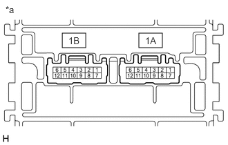
E343054C02
0.938,0.5 1.292,0.719 0.354,0.219 2.094,0.5 2.448,0.719 0.354,0.219 0.083,0.063 0.396,0.219 0.313,0.156 10 false *a 2.188,0.531 2.5,0.688 0.313,0.156 10 false 1A 1.031,0.531 1.344,0.688 0.313,0.156 10 false 1B
*a Component without harness connected
(No. 1 Integration Relay)


Measure the resistance according to the value(s) in the table below.

Standard Resistance:
Tester Connection Condition Specified Condition
1A-4 - 1A-3 Auxiliary battery voltage not applied between terminals 1A-2 and 1A-1 10 kΩ or higher
Auxiliary battery positive (+) → 1A-2
Auxiliary battery negative (-) → 1A-1
Below 1 Ω


If the result is not as specified, replace the No. 1 integration relay.


b.

H-LP LH RELAY:

i.
E343054C02
0.938,0.5 1.292,0.719 0.354,0.219 2.094,0.5 2.448,0.719 0.354,0.219 0.083,0.063 0.396,0.219 0.313,0.156 10 false *a 2.188,0.531 2.5,0.688 0.313,0.156 10 false 1A 1.031,0.531 1.344,0.688 0.313,0.156 10 false 1B
*a Component without harness connected
(No. 1 Integration Relay)


Measure the resistance according to the value(s) in the table below.

Standard Resistance:
Tester Connection Condition Specified Condition
1A-5 - 1B-1 Auxiliary battery voltage not applied between terminals 1A-5 and 1B-2 10 kΩ or higher
Auxiliary battery positive (+) → 1A-5
Auxiliary battery negative (-) → 1B-2
Below 1 Ω


If the result is not as specified, replace the No. 1 integration relay.


c.

EFI-MAIN RELAY:

i.
E343054C02
0.938,0.5 1.292,0.719 0.354,0.219 2.094,0.5 2.448,0.719 0.354,0.219 0.083,0.063 0.396,0.219 0.313,0.156 10 false *a 2.188,0.531 2.5,0.688 0.313,0.156 10 false 1A 1.031,0.531 1.344,0.688 0.313,0.156 10 false 1B
*a Component without harness connected
(No. 1 Integration Relay)


Measure the resistance according to the value(s) in the table below.

Standard Resistance:
Tester Connection Condition Specified Condition
1B-3 - 1B-4 Auxiliary battery voltage not applied between terminals 1B-5 and 1B-6 10 kΩ or higher
Auxiliary battery positive (+) → 1B-5
Auxiliary battery negative (-) → 1B-6
Below 1 Ω


If the result is not as specified, replace the No. 1 integration relay.


d.

IG2 NO. 1 RELAY:

i.
E343054C02
0.938,0.5 1.292,0.719 0.354,0.219 2.094,0.5 2.448,0.719 0.354,0.219 0.083,0.063 0.396,0.219 0.313,0.156 10 false *a 2.188,0.531 2.5,0.688 0.313,0.156 10 false 1A 1.031,0.531 1.344,0.688 0.313,0.156 10 false 1B
*a Component without harness connected
(No. 1 Integration Relay)


Measure the resistance according to the value(s) in the table below.

Standard Resistance:
Tester Connection Condition Specified Condition
1A-10 - 1A-9 Auxiliary battery voltage not applied between terminals 1A-7 and 1A-8 10 kΩ or higher
Auxiliary battery positive (+) → 1A-7
Auxiliary battery negative (-) → 1A-8
Below 1 Ω


If the result is not as specified, replace the No. 1 integration relay.


e.

H-LP RH RELAY:

i.
E343054C02
0.938,0.5 1.292,0.719 0.354,0.219 2.094,0.5 2.448,0.719 0.354,0.219 0.083,0.063 0.396,0.219 0.313,0.156 10 false *a 2.188,0.531 2.5,0.688 0.313,0.156 10 false 1A 1.031,0.531 1.344,0.688 0.313,0.156 10 false 1B
*a Component without harness connected
(No. 1 Integration Relay)


Measure the resistance according to the value(s) in the table below.

Standard Resistance:
Tester Connection Condition Specified Condition
1B-8 - 1A-12 Auxiliary battery voltage not applied between terminals 1B-8 and 1A-11 10 kΩ or higher
Auxiliary battery positive (+) → 1B-8
Auxiliary battery negative (-) → 1A-11
Below 1 Ω


If the result is not as specified, replace the No. 1 integration relay.


f.

P-CON RELAY:

i.
E343054C02
0.938,0.5 1.292,0.719 0.354,0.219 2.094,0.5 2.448,0.719 0.354,0.219 0.083,0.063 0.396,0.219 0.313,0.156 10 false *a 2.188,0.531 2.5,0.688 0.313,0.156 10 false 1A 1.031,0.531 1.344,0.688 0.313,0.156 10 false 1B
*a Component without harness connected
(No. 1 Integration Relay)


Measure the resistance according to the value(s) in the table below.

Standard Resistance:
Tester Connection Condition Specified Condition
1B-9 - 1B-10 Auxiliary battery voltage not applied between terminals 1B-11 and 1B-12 10 kΩ or higher
Auxiliary battery positive (+) → 1B-11
Auxiliary battery negative (-) → 1B-12
Below 1 Ω


If the result is not as specified, replace the No. 1 integration relay.