HEATING / AIR CONDITIONING SOLAR SENSOR INSPECTION
PROCEDURE

 89120A
1.INSPECT AUTOMATIC LIGHT CONTROL SENSOR
Check the wire harness.
Disconnect the automatic light control sensor (K1).
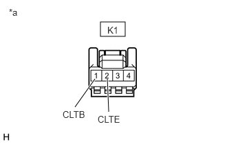
| *a | Front view of wire harness connector
(Automatic Light Control Sensor (Solar Sensor)) |
Measure the voltage according to the value(s) in the table below.
- Standard Voltage:
Tester Connection Switch Condition Specified Condition K1-1(CLTB) - K1-2(CLTE) IG ON 11 to 14 V
If the specified condition is not met, replace the vehicle wire harness.
Check the resistance.
Measure the resistance according to the value(s) in the table below.
- Standard Resistance:
Tester Connection Switch Condition Specified Condition K1-2(CLTE) - Body ground Always Below 1 Ω
If the specified condition is not met, replace the vehicle wire harness.
Check the automatic light control sensor.
Connect the automatic light control sensor (K1).
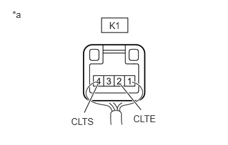
| *a | Component with harness connected
(Automatic Light Control Sensor (Solar Sensor)) |
Check the waveform
Use the oscilloscope and check the waveform in the terminal spaces.
- NOTICE:
-
With the connector connected as is, check from the rear side of the connector.
- Standard:
Tester Connection Switch Condition Standard K1-4(CLTS) - K1-2(CLTE) IG on (IG), light control switch in AUTO position Correct waveform is as shown
If the specified condition is not met, replace the solar sensor.
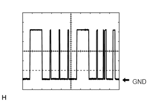
Waveform
| Item | Content |
|---|---|
| Terminal | K1-4(CLTS) - K1-2(CLTE) |
| Equipment Setting | 2V/DIV.,10ms/DIV. |
| Condition | IG on (IG), head light dim switch in AUTO position |
The communication waveform changes according to the surrounding brightness.