METER / GAUGE / DISPLAY METER / GAUGE SYSTEM Entire Combination Meter does not Operate
DESCRIPTION
This circuit is the power source circuit for the combination meter assembly. This circuit provides two types of power sources; one is a constant power source, and the other is an IG power source.
WIRING DIAGRAM
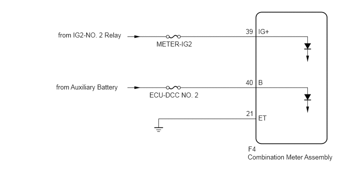
CAUTION / NOTICE / HINT
- NOTICE:
- ·
Inspect the fuses of circuits related to this system before performing the following procedure.
·When replacing the combination meter assembly, always replace it with a new one. If a combination meter assembly which was installed to another vehicle is used, the information stored in it will not match the information from the vehicle and a DTC may be stored.
PROCEDURE
Disconnect the F4 combination meter assembly connector.
Measure the resistance according to the value(s) in the table below.
- Standard Resistance:
Tester Connection Condition Specified Condition F4-21 (ET) - Body ground Always Below 1 Ω
Measure the voltage according to the value(s) in the table below.
- Standard Voltage:
Tester Connection Switch Condition Specified Condition F4-39 (IG+) - Body ground Power switch off Below 1 V Power switch on (IG) 11 to 14 V F4-40 (B) - Body ground Always 11 to 14 V
- Result:
Proceed to OK NG
OK
NG