RM32K0E
_58
Vehicle Interior
_061825
SEAT
_0303903
SEAT HEATER SYSTEM
U
SEAT SEAT HEATER SYSTEM TERMINALS OF ECU
CHECK AIR CONDITIONING AMPLIFIER ASSEMBLY
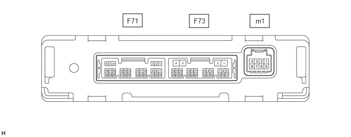
2.51,0.281 2.906,0.552
0.396,0.271
3.865,0.292 4.26,0.563
0.396,0.271
5.104,0.292 5.5,0.563
0.396,0.271
2.594,0.344 3.052,0.542
0.458,0.198
10
false
F71
3.958,0.344 4.417,0.542
0.458,0.198
10
false
F73
5.219,0.344 5.677,0.542
0.458,0.198
10
false
m1
a.
Disconnect the air conditioning amplifier assembly connector.
b.
Measure the voltage and resistance according to the value(s) in the table below.
| Tester Connection | Wiring Color | Terminal Description | Condition | Specified Condition |
|---|---|---|---|---|
| F73-2 (IG+) - Body ground | B - Body ground | IG power supply | Power switch on (IG) | 11 to 14 V |
| Power switch off | Below 1 V | |||
| F73-4 (GND) - Body ground | W-B - Body ground | Ground | Always | Below 1 Ω |
| F73-1 (B) - Body ground | V - Body ground | Auxiliary battery power supply | Always | 11 to 14 V |
c.
Reconnect the air conditioning amplifier assembly connector.
d.
Check for pulse generation according to the value(s) in the table below.
| Tester Connection | Wiring Color | Terminal Description | Condition | Specified Condition |
|---|---|---|---|---|
| F73-14 (LIN1) - Body ground | L*2 - Body ground
BE*1 - Body ground |
Seat heater switch signal | Power switch on (IG) | Pulse generation |
*1: for LHD
*2: for RHD
CHECK AIR CONDITIONING CONTROL ASSEMBLY

3.302,0.229 3.802,0.479
0.5,0.25
3.438,0.271 3.896,0.469
0.458,0.198
10
false
F61
a.
Disconnect the air conditioning control assembly connector.
b.
Measure the voltage and resistance according to the value(s) in the table below.
| Tester Connection | Wiring Color | Terminal Description | Condition | Specified Condition |
|---|---|---|---|---|
| F61-16 (GND) - Body ground | W-B - Body ground | Ground | Always | Below 1 Ω |
| F61-10 (IG+) - F61-16 (GND) | BE - W-B | IG power supply | Power switch on (IG) | 11 to 14 V |
| Power switch off | Below 1 V |
c.
Reconnect the air conditioning control assembly connector.
d.
Measure the voltage according to the value(s) in the table below.
e.
Check for pulse generation according to the value(s) in the table below.
| Tester Connection | Wiring Color | Terminal Description | Condition | Specified Condition |
|---|---|---|---|---|
| F61-2 (LIN1) - F61-16 (GND) | L - W-B | Seat heater switch signal | Power switch on (IG) | Pulse generation |
| F61-4 (RV) - F61-16 (GND) | SB - W-B | Seat heater switch volume signal | Power switch on (IG), seat heater switch (for front passenger side) off | Below 0.6 V |
| Power switch on (IG), seat heater switch (for front passenger side) HI | 3.9 to 5.5 V | |||
| Power switch on (IG), seat heater switch (for front passenger side) MID | 3.4 to 4.7 V | |||
| Power switch on (IG), seat heater switch (for front passenger side) LO | 2.5 to 3.5 V | |||
| F61-11 (SW) - F61-16 (GND) | R - W-B | Seat heater switch volume signal | Power switch on (IG), seat heater switch (for front passenger side) off | Below 1 V |
| Power switch on (IG), seat heater switch (for front passenger side) on | 11 to 14 V | |||
| F61-6 (RV) - F61-16 (GND) | LG - W-B | Seat heater switch volume signal | Power switch on (IG), seat heater switch (for driver side) off | Below 0.6 V |
| Power switch on (IG), seat heater switch (for driver side) HI | 3.9 to 5.5 V | |||
| Power switch on (IG), seat heater switch (for driver side) MID | 3.4 to 4.7 V | |||
| Power switch on (IG), seat heater switch (for driver side) LO | 2.5 to 3.5 V | |||
| F61-12 (SW) - F61-16 (GND) | P - W-B | Seat heater switch volume signal | Power switch on (IG), seat heater switch (for driver side) off | Below 1 V |
| Power switch on (IG), seat heater switch (for driver side) on | 11 to 14 V |