RM32K0E
_56
Audio / Visual / Telematics
_084041
TELEMATICS
_0404728
MAYDAY SWITCH
G
TELEMATICS MAYDAY SWITCH INSPECTION
PROCEDURE

 86750A
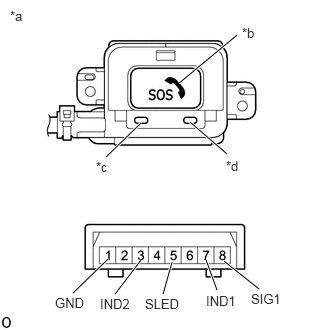
1.INSPECT MAYDAY SWITCH ASSEMBLY
a.
1.125,2.698 0.76,3.052
true
1.469,2.708 1.198,3.063
true
1.792,2.729 1.698,3.063
true
2.146,2.708 2.26,3.021
true
2.333,2.719 2.698,3.01
true
1.469,1.281 1.104,1.635
true
1.979,1.271 2.365,1.604
true
2.469,0.365 1.865,0.865
true
0.104,0.083 0.417,0.24
0.313,0.156
10
false
*a
0.573,3.073 0.927,3.25
0.354,0.177
10
false
GND
1.042,3.083 1.396,3.26
0.354,0.177
10
false
IND2
2.146,3.052 2.5,3.229
0.354,0.177
10
false
IND1
2.615,3.031 2.969,3.208
0.354,0.177
10
false
SIG1
1.51,3.083 1.969,3.26
0.458,0.177
10
false
SLED
1,1.656 1.313,1.813
0.313,0.156
10
false
*c
2.354,1.646 2.667,1.802
0.313,0.156
10
false
*d
2.521,0.26 2.833,0.417
0.313,0.156
10
false
*b
| *a | Component without harness connected
(Mayday Switch Assembly) |
| *b | SOS Switch |
| *c | Green Indicator |
| *d | Red Indicator |
Check the resistance.
i.
Measure the resistance according to the value(s) in the table below.
- Standard Resistance:
Tester Connection Condition Specified Condition 8 (SIG1) - 1 (GND) Mayday switch is pushed 78 to 86 Ω 8 (SIG1) - 1 (GND) Mayday switch is not pushed 392 to 432 Ω
If the resistance is not as specified, replace the mayday switch assembly.
b.
Check the switch illumination.
i.
Apply auxiliary battery voltage to the mayday switch assembly and check that the illumination comes on.
- OK:
Auxiliary Battery Connection Specified Condition Auxiliary battery positive (+) → 5 (SLED)
Auxiliary battery negative (-) → 1 (GND)SOS switch comes on
If the resistance is not as specified, replace the mayday switch assembly.
c.
Check the indicator illumination.
i.
Apply auxiliary battery voltage to the mayday switch assembly and check that the illumination comes on.
- OK:
Auxiliary Battery Connection Specified Condition Auxiliary battery positive (+) → 7 (IND1)
Auxiliary battery negative (-) → 1 (GND)Red indicator comes on Auxiliary battery (+) → 3 (IND2)
Auxiliary battery (-) → 1 (GND)Green indicator comes on
If the resistance is not as specified, replace the mayday switch assembly.