LIGHTING (EXT) LIGHTING SYSTEM(w/o Headlight ECU) Footwell Light Circuit
DESCRIPTION
The main body ECU (multiplex network body ECU) controls the door mirror foot lights.
WIRING DIAGRAM
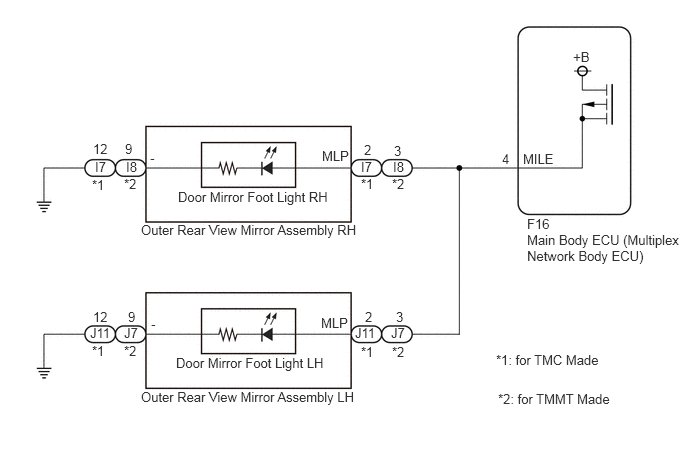
PROCEDURE
Connect the GTS to the DLC3.
Turn the power switch to on (IG).
Turn the GTS on.
Enter the following menus: Body Electrical / Main Body / Active Test.
Perform the Active Test according to the display on the GTS.
- Body Electrical > Main Body > Active Test
-
Tester Display Measurement Item Control Range Diagnostic Note Side Mirror Foot Light Door mirror foot lights ON/OFF -
- Body Electrical > Main Body > Active Test
-
Tester Display Side Mirror Foot Light - 50004 123 32
- OK:
Door mirror foot lights illuminate.
- Result:
Proceed to OK NG
OK
Click hereVehicle Exterior>LIGHTING (EXT)>LIGHTING SYSTEM (w/o Headlight ECU)>PROBLEM SYMPTOMS TABLE
NG
Disconnect the J11*1 or J7*2 rear view mirror assembly LH.
*1: for TMMT Made
*2: for TMC Made
Disconnect the I7*1 or I8*2 rear view mirror assembly RH.
*1: for TMMT Made
*2: for TMC Made
Disconnect the F16 main body ECU (multiplex network body ECU) connector.
Measure the resistance according to the value(s) in the table below.
- Standard Resistance:
for TMMT Made Tester Connection Condition Specified Condition J11-2 (MLP) or I7-2 (MLP) - F16-4 (MILE) Always Below 1 Ω J11-2 (MLP) or F16-4 (MILE) -Body ground Always 10 kΩ or higher I7-2 (MLP) or F16-4 (MILE) -Body ground Always 10 kΩ or higher
- Standard Resistance:
for TMC Made Tester Connection Condition Specified Condition J7-3 (MLP) or I8-3 (MLP) - F16-4 (MILE) Always Below 1 Ω J7-3 (MLP) or F16-4 (MILE) -Body ground Always 10 kΩ or higher I8-3 (MLP) or F16-4 (MILE) -Body ground Always 10 kΩ or higher
- Result:
Proceed to OK NG
OK
NG