RM32K0E
_56
Audio / Visual / Telematics
_061817
AUDIO / VIDEO
_0525784
AUDIO AND VISUAL SYSTEM(for Radio and Display Type with Single Knob Type)
C
AUDIO / VIDEO AUDIO AND VISUAL SYSTEM(for Radio and Display Type with Single Knob Type) B1ADF71 Sub Woofer Speaker Cable Actuator Stuck
DESCRIPTION
This DTC is stored when the stereo component amplifier assembly detects an open in the sub-woofer speaker circuit by energizing the speaker line.
| DTC No. | Detection Item | DTC Detection Condition | Trouble Area |
|---|---|---|---|
| B1ADF71 | Sub Woofer Speaker Cable Actuator Stuck | Open in the sub-woofer speaker circuit is detected.
(1 trip detection logic) |
·
Harness or connector ·
Stereo component amplifier assembly ·
No. 1 speaker with box assembly |
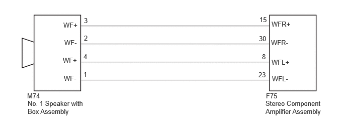
WIRING DIAGRAM
5.51,1.906 5.969,2.104
0.458,0.198
10
false
F75
5.5,2.063 6.708,2.531
1.208,0.469
10
false
Stereo Component Amplifier Assembly
5.625,0.417 6.115,0.604
0.49,0.188
10
false
WFR+
5.635,1.552 6.094,1.75
0.458,0.198
10
false
WFL-
0.573,2.063 1.813,2.479
1.24,0.417
10
false
No. 1 Speaker with Box Assembly
0.563,1.906 1.021,2.104
0.458,0.198
10
false
M74
1.74,0.708 1.948,0.906
0.208,0.198
10
false
2
1.729,1.458 1.938,1.656
0.208,0.198
10
false
1
5.375,0.323 5.625,0.531
0.25,0.208
10
false
15
5.354,1.469 5.563,1.667
0.208,0.198
10
false
23
1.313,0.438 1.771,0.635
0.458,0.198
10
false
WF+
1.333,0.802 1.792,1
0.458,0.198
10
false
WF-
1.323,1.542 1.781,1.74
0.458,0.198
10
false
WF-
1.302,1.167 1.76,1.365
0.458,0.198
10
false
WF+
1.74,0.344 1.948,0.542
0.208,0.198
10
false
3
1.729,1.094 1.938,1.292
0.208,0.198
10
false
4
5.365,0.719 5.615,0.927
0.25,0.208
10
false
30
5.427,1.094 5.677,1.302
0.25,0.208
10
false
8
5.615,0.802 6.104,0.99
0.49,0.188
10
false
WFR-
5.625,1.208 6.083,1.406
0.458,0.198
10
false
WFL+
PROCEDURE
1.CHECK HARNESS AND CONNECTOR (STEREO COMPONENT AMPLIFIER ASSEMBLY - NO. 1 SPEAKER WITH BOX ASSEMBLY)
a.
Disconnect the F75 stereo component amplifier assembly connector.
b.
Disconnect the M74 No. 1 speaker with box assembly connector.
c.
Measure the resistance according to the value(s) in the table below.
- Standard Resistance:
Tester Connection Condition Specified Condition F75-15 (WFR+) - M74-3 (WF+) Always Below 1 Ω F75-30 (WFR-) - M74-2 (WF-) Always Below 1 Ω F75-8 (WFL+) - M74-4 (WF+) Always Below 1 Ω F75-23 (WFL-) - M74-1 (WF-) Always Below 1 Ω
- Result:
Proceed to OK NG
OK
2.INSPECT NO. 1 SPEAKER WITH BOX ASSEMBLY
NG
REPAIR OR REPLACE HARNESS OR CONNECTOR
2.INSPECT NO. 1 SPEAKER WITH BOX ASSEMBLY
Click hereAudio / Visual / Telematics>AUDIO / VIDEO>FRONT DOOR SPEAKER>INSPECTION
- Result:
Proceed to OK NG
OK
3.CHECK FOR DTC
NG
REPLACE NO. 1 SPEAKER WITH BOX ASSEMBLY
3.CHECK FOR DTC
a.
Clear the DTCs.
- Body Electrical > Navigation System > Clear DTCs
- 50002 496
b.
In accordance with the display of the GTS, perform a speaker circuit energization inspection.
- Body Electrical > Navigation System > Utility
-
Tester Display Speaker Line Electricity Check - 50005 496 4768
c.
Check for DTCs and proceed to the following step.
- Body Electrical > Navigation System > Trouble Codes
- 50001 496
- Result:
Result Proceed to DTCs are not output A DTC B1ADF71 is output B
A
END (NO. 1 SPEAKER WITH BOX ASSEMBLY IS DEFECTIVE)
B
REPLACE STEREO COMPONENT AMPLIFIER ASSEMBLY