Home › Vehicle Interior › HEATING / AIR CONDITIONING › AIR CONDITIONING SYSTEM
NM32H0E _58 Vehicle Interior _059732 HEATING / AIR CONDITIONING _0292851 AIR CONDITIONING SYSTEM DE DETAILS F

HEATING / AIR CONDITIONING  AIR CONDITIONING SYSTEM  DETAILS  SERVO MOTOR  


CONSTRUCTION


a.

Stepper Motor Type Servo Motor

i.

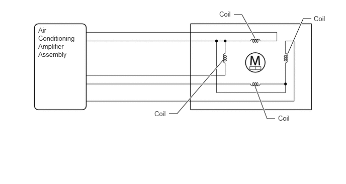
A stepper motor type servo motor is used on except models with dual air layer type air conditioning unit for RHD.


ii.

Battery voltage is continuously applied to the 4 coils inside the motor, and the air conditioning amplifier assembly turns each coil on and off in sequence for the precise number of times necessary in order to reach the target position.
Y208294E01
5.958,1.115 6.281,0.385 6.281,0.385 6.448,0.385 true 3.5,2.354 3.667,2.354 3.667,2.354 4.615,1.25 true 5.281,1.781 5.531,2.458 5.531,2.458 5.698,2.458 true 4.844,0.302 5.01,0.302 5.01,0.302 5.281,0.792 true 0.792,0.542 1.573,1.469 0.781,0.927 10 false Air Conditioning Amplifier Assembly 4.542,0.208 5.073,0.448 0.531,0.24 10 false Coil 6.5,0.302 7.031,0.542 0.531,0.24 10 false Coil 5.76,2.365 6.292,2.604 0.531,0.24 10 false Coil 3.198,2.271 3.729,2.51 0.531,0.24 10 false Coil


b.

Pulse Pattern Type Servo Motor

i.

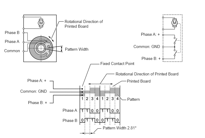
A pulse pattern type servo motor is used on models with dual air layer type air conditioning unit for RHD.


ii.

In contrast to the previous type of servo motor that detects the position by way of potentiometer voltage, the pulse pattern type servo motor detects the relative position by way of 2-bit on/off signals.


iii.

The forward and reverse revolutions of this type of servo motor are detected by way of 2 phases, A and B, which output 4 types of patterns. The air conditioning amplifier assembly counts the number of pulse patterns in order to determine the stopped position.
Y111171E15
4,2.583 3.729,2.583 3.729,2.583 3.5,2.927 false 3.479,2.24 3.167,2.24 3.167,2.24 2.875,3.021 true 3.938,3.021 4.25,2.833 4.25,2.833 4.417,2.833 true 4.104,3.292 4.271,3.49 4.271,3.49 4.417,3.49 true 3.271,4.635 3.417,4.49 3.417,4.49 3.542,4.49 true 2.229,0.75 2.063,0.75 2.063,0.75 1.802,1.333 true 0.167,1.052 0.781,1.385 0.615,0.333 10 false Phase B 0.167,1.365 0.781,1.698 0.615,0.333 10 false Phase A 0.146,1.688 0.76,2.021 0.615,0.333 10 false Common 2.26,0.667 3.646,1.26 1.385,0.594 10 false Rotational Direction of Printed Board 2.271,1.635 3.188,1.979 0.917,0.344 10 false Pattern Width 0.958,2.729 1.74,3.073 0.781,0.344 10 false Phase A: + 4.927,1.115 5.708,1.458 0.781,0.344 10 false Phase A: + 0.979,3.5 1.76,3.844 0.781,0.344 10 false Phase B: + 4.948,1.958 5.729,2.302 0.781,0.344 10 false Phase B: + 4.438,2.75 5.385,3.094 0.948,0.344 10 false Printed Board 4.042,2.5 6.427,2.844 2.385,0.344 10 false Rotational Direction of Printed Board 3.51,2.135 4.813,2.479 1.302,0.344 10 false Fixed Contact Point 4.448,3.385 5.229,3.729 0.781,0.344 10 false Pattern 2.188,3.771 2.792,4.115 0.604,0.344 10 false Phase A 2.188,4.125 2.792,4.469 0.604,0.344 10 false Phase B 0.708,3.104 1.75,3.448 1.042,0.344 10 false Common: GND 4.667,1.542 5.708,1.885 1.042,0.344 10 false Common: GND 3.594,4.385 4.917,4.74 1.323,0.354 10 false Pattern Width 2.81°