Home › Engine / Hybrid System › 3ZR-FAE (ENGINE CONTROL) › SFI SYSTEM
NM32H0E _51 Engine / Hybrid System _060218 3ZR-FAE ENGINE CONTROL _0295413 SFI SYSTEM CO CONTROL F

3ZR-FAE ENGINE CONTROL  SFI SYSTEM  CONTROL  VALVEMATIC CONTROL  


FUNCTION


a.

The VALVEMATIC System effects coordinated control with the dual VVT-i system. It performs effects continuously variable control of the amount of intake valve lift, intake valve action angle and intake valve timing, as well as control of the exhaust valve timing, in accordance with the engine operating conditions. This results in improved engine performance and better fuel economy.


b.

The intake valve action angle varies between 106° CA and 280° CA, and the amount of intake valve lift varies between 1.1 mm (0.0433 in.) and 11.5 mm (0.453 in.).


c.

The VALVEMATIC System consists of a continuously variable valve lift controller assembly at the actuator and VALVEMATIC mechanism.


d.

Along with the use of this system, a vacuum pump assembly is provided in order to provide proper brake control vacuum.
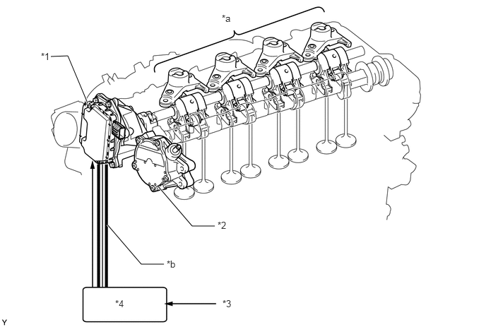
W116865C01
1.292,1.521 1,0.823 1,0.823 0.75,0.833 true 2.333,2.75 2.833,3.333 2.833,3.333 3.167,3.333 true 1.583,3.313 2.083,3.896 2.083,3.896 2.417,3.896 true 3.271,0.188 3.583,0.385 0.313,0.198 10 false *a 3.208,3.24 3.521,3.438 0.313,0.198 10 false *2 0.604,0.75 0.917,0.948 0.313,0.198 10 false *1 2.458,3.813 2.771,4.01 0.313,0.198 10 false *b 1.698,4.396 2.01,4.594 0.313,0.198 10 false *4 3.281,4.396 3.594,4.594 0.313,0.198 10 false *3
*1 Continuously Variable Valve Lift Controller Assembly
·

EDU

·

Motor Position Sensor

·

Action Angle Sensor


*2 Vacuum Pump Assembly
*3 Various Sensors *4 ECM
*a VALVEMATIC Mechanism *b CAN (Local Bus)


e.

The continuously variable valve lift controller assembly operates the VALVEMATIC mechanism in accordance with signals from the ECM in order to control the amount of intake valve lift and the intake valve action angle.


f.

The VALVEMATIC system effects coordinated control with the dual VVT-i system and ETCS-i.
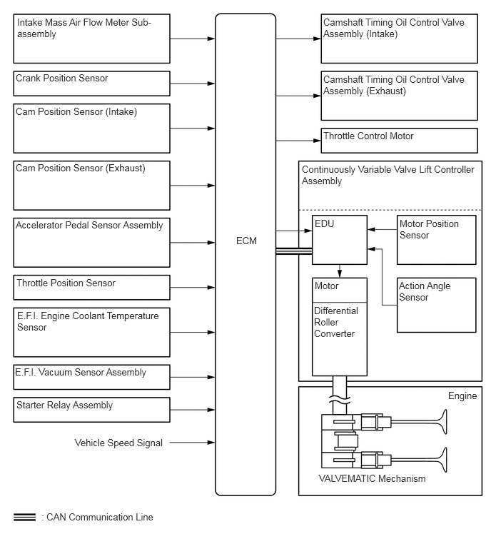
W133586E01
0.25,0.24 2.292,0.594 2.042,0.354 10 false Intake Mass Air Flow Meter Sub-assembly 0.229,1.052 2.438,1.406 2.208,0.354 10 false Crank Position Sensor 0.229,1.542 2.438,1.896 2.208,0.354 10 false Cam Position Sensor (Intake) 0.229,2.365 2.438,2.719 2.208,0.354 10 false Cam Position Sensor (Exhaust) 0.229,3.198 2.552,3.552 2.323,0.354 10 false Accelerator Pedal Sensor Assembly 0.24,4.042 2.448,4.396 2.208,0.354 10 false Throttle Position Sensor 0.25,4.521 2.385,4.875 2.135,0.354 10 false E.F.I. Engine Coolant Temperature Sensor 0.219,5.344 2.427,5.698 2.208,0.354 10 false E.F.I. Vacuum Sensor Assembly 0.24,5.823 2.448,6.177 2.208,0.354 10 false Starter Relay Assembly 1.094,6.375 3.302,6.729 2.208,0.354 10 false Vehicle Speed Signal 0.604,7.458 2.813,7.813 2.208,0.354 10 false : CAN Communication Line 3.448,3.427 4.063,3.875 0.615,0.448 10 false ECM 4.719,0.24 6.833,0.583 2.115,0.344 10 false Camshaft Timing Oil Control Valve Assembly (Intake) 4.719,1.073 6.813,1.427 2.094,0.354 10 false Camshaft Timing Oil Control Valve Assembly (Exhaust) 4.719,1.896 6.927,2.25 2.208,0.354 10 false Throttle Control Motor 4.406,2.385 6.969,2.833 2.563,0.448 10 false Continuously Variable Valve Lift Controller Assembly 4.594,3.177 5.323,3.625 0.729,0.448 10 false EDU 5.833,3.177 6.74,3.646 0.906,0.469 10 false Motor Position Sensor 5.823,4.083 6.635,4.583 0.813,0.5 10 false Action Angle Sensor 4.594,4.083 5.677,4.333 1.083,0.25 10 false Motor 4.583,4.448 5.271,5 0.688,0.552 10 false Differential Roller Converter 4.656,6.896 6.615,7.229 1.958,0.333 10 false VALVEMATIC Mechanism 6.542,5.688 7.156,6.135 0.615,0.448 10 false Engine


g.

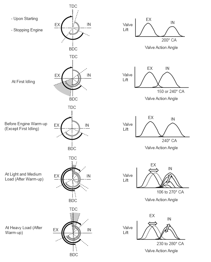
The VALVEMATIC system controls the amount of intake valve lift, intake valve action angle, intake valve timing and exhaust valve timing in order to achieve the following effects:
W113503E01
0.375,0.542 1.365,0.792 0.99,0.25 10 false - Upon Starting 0.375,0.927 1.521,1.167 1.146,0.24 10 false - Stopping Engine 0.396,2.677 1.542,2.917 1.146,0.24 10 false At First Idling 0.156,4.104 1.656,4.656 1.5,0.552 10 false Before Engine Warm-up (Except First Idling) 0.167,5.813 1.5,6.281 1.333,0.469 10 false At Light and Medium Load (After Warm-up) 0.177,7.625 1.479,8.104 1.302,0.479 10 false At Heavy Load (After Warm-up) 2.344,0.125 2.688,0.302 0.344,0.177 10 false TDC 2.354,1.833 2.677,1.99 0.323,0.156 10 false TDC 2.302,3.552 2.646,3.729 0.344,0.177 10 false TDC 2.333,5.271 2.677,5.448 0.344,0.177 10 false TDC 2.354,7 2.698,7.177 0.344,0.177 10 false TDC 2.948,0.74 3.292,0.917 0.344,0.177 10 false IN 1.854,0.75 2.198,0.927 0.344,0.177 10 false EX 1.854,2.469 2.198,2.646 0.344,0.177 10 false EX 2.948,2.458 3.177,2.646 0.229,0.188 10 false IN 2.885,4.156 3.115,4.344 0.229,0.188 10 false IN 2.938,5.875 3.167,6.063 0.229,0.188 10 false IN 1.833,4.156 2.177,4.333 0.344,0.177 10 false EX 1.833,5.875 2.177,6.052 0.344,0.177 10 false EX 1.802,7.698 2.146,7.875 0.344,0.177 10 false EX 2.958,7.698 3.188,7.885 0.229,0.188 10 false IN 2.344,1.573 2.688,1.75 0.344,0.177 10 false BDC 2.354,3.271 2.698,3.448 0.344,0.177 10 false BDC 2.302,4.948 2.646,5.125 0.344,0.177 10 false BDC 2.333,6.708 2.677,6.885 0.344,0.177 10 false BDC 2.365,8.542 2.708,8.719 0.344,0.177 10 false BDC 4.177,0.75 4.542,1.156 0.365,0.406 10 false Valve Lift 4.167,2.448 4.531,2.854 0.365,0.406 10 false Valve Lift 4.177,4.125 4.542,4.531 0.365,0.406 10 false Valve Lift 4.177,5.854 4.542,6.26 0.365,0.406 10 false Valve Lift 4.177,7.625 4.542,8.031 0.365,0.406 10 false Valve Lift 4.958,0.573 5.302,0.75 0.344,0.177 10 false EX 5,2.229 5.344,2.406 0.344,0.177 10 false EX 5.031,3.896 5.375,4.073 0.344,0.177 10 false EX 5.115,5.5 5.458,5.677 0.344,0.177 10 false EX 5.073,7.219 5.417,7.396 0.344,0.177 10 false EX 5.677,7.333 5.906,7.521 0.229,0.188 10 false IN 5.708,5.625 5.938,5.813 0.229,0.188 10 false IN 5.802,3.948 6.031,4.135 0.229,0.188 10 false IN 5.615,2.229 5.844,2.417 0.229,0.188 10 false IN 5.792,0.677 6.021,0.865 0.229,0.188 10 false IN 4.927,1.521 6.125,1.75 1.198,0.229 10 false Valve Action Angle 4.927,3.25 6.125,3.479 1.198,0.229 10 false Valve Action Angle 4.927,4.917 6.125,5.146 1.198,0.229 10 false Valve Action Angle 4.927,6.677 6.125,6.906 1.198,0.229 10 false Valve Action Angle 4.927,8.406 6.125,8.635 1.198,0.229 10 false Valve Action Angle 5.49,1.271 6.104,1.479 0.615,0.208 10 false 200° CA 5.333,3.01 6.365,3.208 1.031,0.198 10 false 150 or 240° CA 5.5,4.677 6.115,4.885 0.615,0.208 10 false 240° CA 5.323,6.417 6.333,6.635 1.01,0.219 10 false 106 to 270° CA 5.323,8.167 6.313,8.385 0.99,0.219 10 false 230 to 280° CA

Operation State Amount of Valve Lift/Valve Action Angle Objective Effect

*: During cranking, if the ECM determines that the engine has started, the intake valve action angle moves to 240° CA.

Upon Starting/Stopping Engine Intake valve action angle is fixed at 200° CA.* Reducing overlap to improve compression ratio Improved startability
At First Idling Intake valve action angle is fixed at 150 or 240° CA. Increasing overlap to increase internal EGR Improved emission control
Before Engine Warm-up (Except First Idling) Intake valve action angle is fixed at 240° CA. Improving intake air charging efficiency
·

Improved output

·

Better fuel economy


At Light and Medium Load (After Warm-up)
·

Effects coordinated control with dual VVT-i and ETCS-i.

·

Amount of intake valve lift is variable.

·

Intake valve action angle is variable within a range of 106 to 270° CA.


Closing the intake valve early to reduce pumping loss Better fuel economy
At Heavy Load (After Warm-up)
·

Effects coordinated control with dual VVT-i.

·

Amount of intake valve lift is variable.

·

Intake valve action angle is variable within a range between 230 and 280° CA.


Closing the intake valve late, thus retarding the injection timing, to improve volumetric efficiency
·

Improved output

·

Better fuel economy

·

Reduction of exhaust gas temperature