3ZR-FAE BATTERY / CHARGING CHARGING SYSTEM DETAILS GENERATOR
CONSTRUCTION
Stator Coil
The joined segment method is used for the stator coil. In this method, segment conductors are inserted and welded together to form the stator. This enables a smaller body, yet higher output, and higher efficiency. By providing a mesh ventilation gap between the coil ends, the coil end inner circumference surfaces that receive the cool wind are smoothened to allow wind to flow smoothly, improving cooling performance and reducing the sound of the wind.
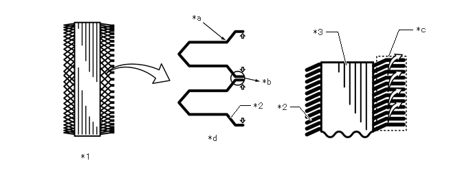
| *1 | Stator | *2 | Segment |
| *3 | Stator Core | - | - |
| *a | Twisting | *b | Joint |
| *c | Ventilation Gap | *d | Joined Segment Method |
Generator Pulley
A clutch is set to the generator pulley.
Operation of the clutch cancels generator pulley inertia and helps to prevent slipping of the fan and generator V belt. This realizes a low tension fan and generator V belt that achieves reduced friction.
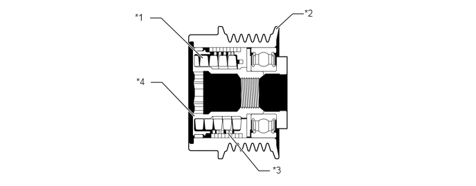
| *1 | Coil Spring | *2 | Pulley |
| *3 | Clutch | *4 | Shaft |
OPERATION
Stator Coil
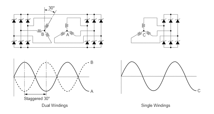
A dual winding system is used. This system consists of 2 sets of three-phase windings whose phase are staggered 30°. This system results in the reduction of both electrical noise (ripple and spike), and magnetic noise (a hum that is heard as generator load is increased). This system significantly suppresses noise at the source (generator). Because the waves that the respective windings generate have opposite polarities, magnetic noise is reduced. The magnetic noise is significantly reduced, but the electrical power generated does not cancel itself out, due to the use of separate rectifiers. The opposite polarities that are generated can be seen below.
SPECIFICATION
| Item | Specification |
|---|---|
| Generator Type | SC1 |
| Rated Voltage | 12 V |
| Output Rated | 130 A |
| Initial Output Starting Speed | Max. 1300 rpm |