Home › Engine / Hybrid System › 8NR-FTS (ENGINE CONTROL) › SFI SYSTEM › 2016.10–2018.05
NM32H0E _51 Engine / Hybrid System _060396 8NR-FTS ENGINE CONTROL _0296167 SFI SYSTEM CO CONTROL F

8NR-FTS ENGINE CONTROL  SFI SYSTEM  CONTROL  VVT-iW CONTROL  


FUNCTION


a.

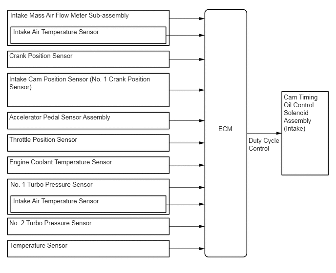
The Variable Valve Timing-intelligent Wide (VVT-iW) control is designed to control the intake camshaft within a range of 70° respectively (of crankshaft angle) to provide valve timing optimally suited to the engine condition. This improves torque in all speed ranges as well as increasing fuel economy and reducing exhaust emissions.


b.

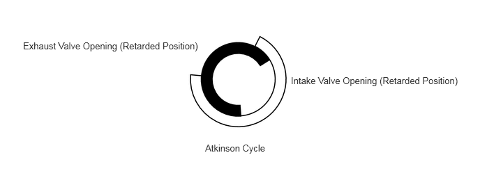
The operation angle for the VVT-iW has been made larger for the retarded side compared to the VVT-i. During partial load driving, the Atkinson cycle is entered, pumping loss is further reduced and fuel economy is enhanced.
W134785E01
0.219,0.24 2.917,0.521 2.698,0.281 10 false Intake Mass Air Flow Meter Sub-assembly 0.281,0.594 2.979,0.875 2.698,0.281 10 false Intake Air Temperature Sensor 0.198,1.104 2.896,1.385 2.698,0.281 10 false Crank Position Sensor 0.198,1.604 3.333,2.042 3.135,0.438 10 false Intake Cam Position Sensor (No. 1 Crank Position Sensor) 0.198,2.417 2.896,2.698 2.698,0.281 10 false Accelerator Pedal Sensor Assembly 0.198,2.896 2.896,3.177 2.698,0.281 10 false Throttle Position Sensor 0.198,3.375 2.896,3.656 2.698,0.281 10 false Engine Coolant Temperature Sensor 0.219,3.854 2.917,4.135 2.698,0.281 10 false No. 1 Turbo Pressure Sensor 0.281,4.208 2.573,4.469 2.292,0.26 10 false Intake Air Temperature Sensor 0.198,4.677 2.896,4.958 2.698,0.281 10 false No. 2 Turbo Pressure Sensor 0.208,5.156 2.865,5.417 2.656,0.26 10 false Temperature Sensor 4.656,2.667 5.115,2.865 0.458,0.198 10 false ECM 5.302,2.917 6.01,3.469 0.708,0.552 10 false Duty Cycle Control 6.052,1.99 6.823,3.104 0.771,1.115 10 false Cam Timing Oil Control Solenoid Assembly (Intake)


c.

In order to ensure engine startability, an intermediate lock mechanism is used for the VVT-iW. For details, see VVT-iW CONTROLLER in the 8NR-FTS ENGINE MECHANICAL section.


d.

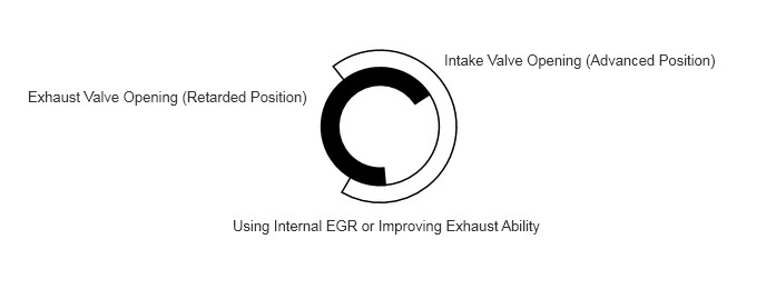
The following effects can be achieved due to the advanced angle and retarded angle of the intake and exhaust valves.
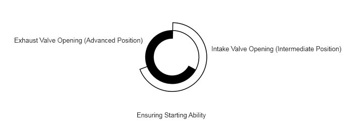
Operation Model Diagram: Upon Starting and Idling
W122749E03
4.365,0.927 7.083,1.281 2.719,0.354 10 false Intake Valve Opening (Intermediate Position) 0.292,0.75 3.01,1.115 2.719,0.365 10 false Exhaust Valve Opening (Advanced Position) 2.823,2.302 4.385,2.542 1.563,0.24 10 false Ensuring Starting Ability

Operation Model Diagram: At Partial Load
W122750E02
3.063,2.135 4.135,2.51 1.073,0.375 10 false Atkinson Cycle 0.344,0.604 3,1 2.656,0.396 10 false Exhaust Valve Opening (Retarded Position) 4.344,1.125 6.896,1.521 2.552,0.396 10 false Intake Valve Opening (Retarded Position)

Operation Model Diagram: At Partial Load to Heavy Load
W122751E02
2.177,2.031 5.208,2.427 3.031,0.396 10 false Using Internal EGR or Improving Exhaust Ability 0.26,0.823 2.958,1.302 2.698,0.479 10 false Exhaust Valve Opening (Retarded Position) 4.156,0.479 6.802,0.823 2.646,0.344 10 false Intake Valve Opening (Advanced Position)


e.

The ECM cooperatively controls the throttle valve, VVT-iW, VVT-i and wastegate valve of the turbocharger sub-assembly to achieve a driving condition with optimal fuel economy during normal driving. Also, the ECM controls each actuator in accordance with the driver's intentions during acceleration to achieve a high torque response.