8NR-FTS ENGINE CONTROL SFI SYSTEM CONTROL ELECTRICAL SPARK ADVANCE (ESA) CONTROL
FUNCTION
The Direct Ignition System (DIS) is used. Each ignition coil assembly is equipped with a built-in igniter, and one ignition coil assembly is provided for each cylinder.
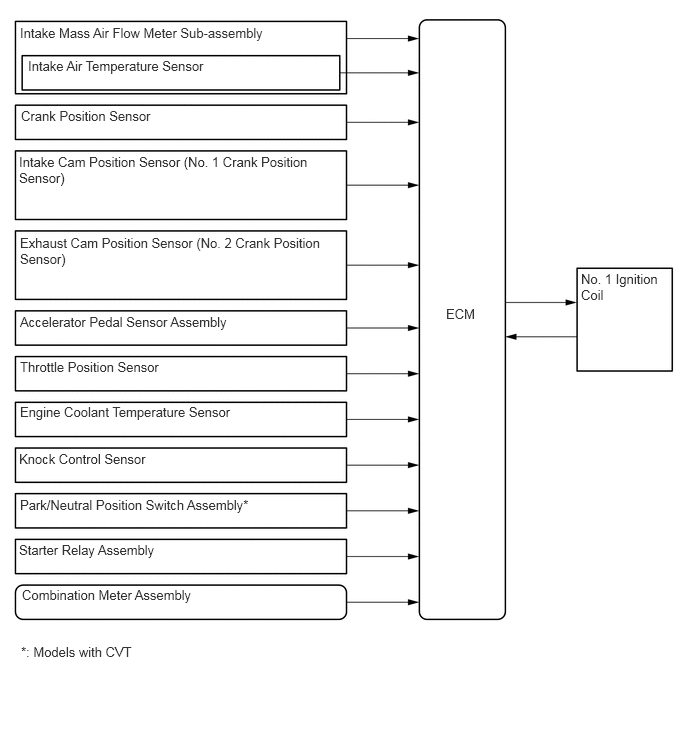
The ECM calculates the most appropriate ignition timing and the time that current is applied to the primary windings of the ignition coil based on the signals sent from various sensors. The ECM then sends an ignition command signal to the igniter of the ignition coil assembly.
The ignition timing is obtained using the following formula:
Ignition timing = A or B + C
Where: A: Base ignition timing, B: Basic advance, C: Compensation advance
| A. Fixed advance characteristics | The base ignition timing is 10° BTDC. It is fixed at 5° BTDC while the engine is starting. |
| B. Basic advance characteristics | The most appropriate ignition timing is selected from a map based on the signals from a variety of sensors. |
| C. Compensation advance characteristics | The ignition timing is advanced or retarded depending on the signals from a variety of sensors. |
| C-1. Warm engine advance characteristics | When the engine coolant temperature is low, the ignition timing is advanced in accordance with driving conditions to enhance drivability. |
| C-2. Idle stabilization advance characteristics | If the idle speed drops, the ignition timing is advanced to stabilize the idle speed. If the idle speed increases, the ignition timing is retarded. |
| C-3. Transition compensation retard | To prevent knocking, the ignition timing is retarded during sudden acceleration at a coolant temperature of 60°C (140°F) or more. |
| C-4. Retard when accelerating | The ignition timing is temporarily retarded during acceleration to enhance drivability. |
| C-5. Knock compensation retard | If knock occurs, the ignition timing is corrected based on the signal from the knock sensor. |
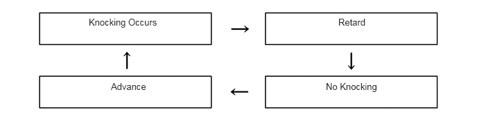
If engine knocking is detected, the ignition timing is retarded gradually in equal steps according to the size of knocking, until the engine stops knocking.
After knocking has stopped, the ignition timing is advanced gradually in equal steps. If the engine knocks again during this process, then the ignition timing is retarded again.