NM32H0E
_52
Drivetrain
_062153
K313 MULTIDRIVE / CVT
_0302987
CVT SYSTEM
DE
DETAILS
F
K313 MULTIDRIVE / CVT CVT SYSTEM DETAILS SHIFT CONTROL
CONSTRUCTION
a.
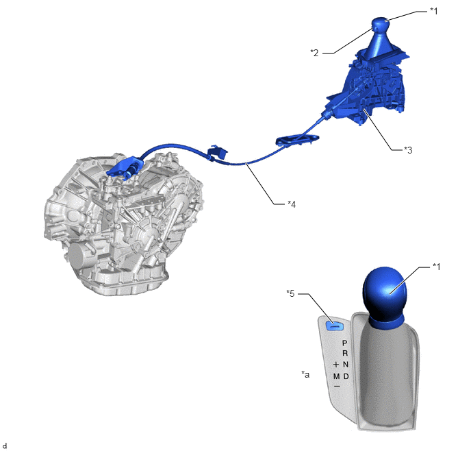
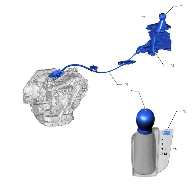
A straight type shift lever with boot that uses a transmission control cable assembly is used.
b.
The shift control mechanism consists of a shift lock control unit assembly, a shift lever knob sub-assembly and a transmission control cable assembly.
c.
A shift lever cap is provided on the shift lock release button to prevent erroneous operation.
LHD Models
5.854,0.323 6.333,0.177
6.333,0.177 6.5,0.177
true
4.906,0.813 5.073,0.813
5.073,0.813 5.667,0.427
true
5.531,1.656 5.958,2.281
5.958,2.281 6.125,2.281
true
3.74,2.479 4.167,3.104
4.167,3.104 4.333,3.104
true
4.531,4.469 4.698,4.469
4.698,4.469 5.073,4.917
true
5.927,4.469 6.375,4.063
6.375,4.063 6.542,4.063
true
6.542,0.083 6.854,0.24
0.313,0.156
10
false
*1
4.719,0.719 5.031,0.875
0.313,0.156
10
false
*2
6.146,2.198 6.458,2.354
0.313,0.156
10
false
*3
4.375,3.021 4.688,3.177
0.313,0.156
10
false
*4
4.354,4.375 4.667,4.531
0.313,0.156
10
false
*5
4.583,5.604 4.896,5.76
0.313,0.156
10
false
*a
6.583,3.969 6.896,4.125
0.313,0.156
10
false
*1
| *1 | Shift Lever Knob Sub-assembly | *2 | Shift Lever Knob button |
| *3 | Shift Lock Control Unit Assembly | *4 | Transmission Control Cable Assembly |
| *5 | Shift Lock Release Button Cap | - | - |
| *a | Shift Pattern | - | - |
RHD Models
6.01,0.563 6.333,0.25
6.333,0.25 6.5,0.25
true
5.625,1.854 6,2.417
6,2.417 6.167,2.417
true
3.969,2.625 4.302,3.104
4.302,3.104 4.469,3.104
true
5.344,4.083 5.073,3.365
5.073,3.365 4.906,3.365
true
6.083,4.833 6.458,4.073
6.458,4.073 6.625,4.073
true
5.427,0.656 5.844,0.656
true
6.563,0.146 6.875,0.302
0.313,0.156
10
false
*1
5.188,0.563 5.5,0.719
0.313,0.156
10
false
*2
6.229,2.313 6.542,2.469
0.313,0.156
10
false
*3
4.552,3 4.865,3.156
0.313,0.156
10
false
*4
6.677,3.99 6.99,4.146
0.313,0.156
10
false
*5
6.333,5.375 6.646,5.531
0.313,0.156
10
false
*a
4.729,3.26 5.042,3.417
0.313,0.156
10
false
*1
| *1 | Shift Lever Knob Sub-assembly | *2 | Shift Lever Knob button |
| *3 | Shift Lock Control Unit Assembly | *4 | Transmission Control Cable Assembly |
| *5 | Shift Lock Release Button Cap | - | - |
| *a | Shift Pattern | - | - |
d.
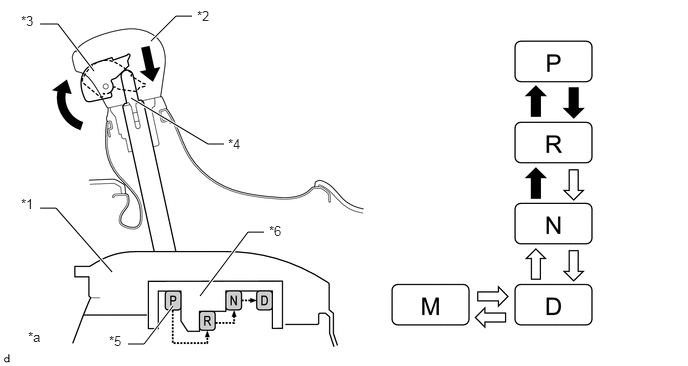
The shift lever used is a 5-position (P, R, N, D and M) straight type lever. Along with the change to a straight-type lever, a detent mechanism using knob button operation was added to prevent accidentally shifting from P→R, R→P, or N→R.
1.573,0.427 1.833,0.167
1.833,0.167 2,0.167
true
1.365,1.021 2.167,1.5
2.167,1.5 2.333,1.5
true
2.083,3.083 2.583,2.417
2.583,2.417 2.75,2.417
true
1.333,3.583 1.5,3.583
1.5,3.583 1.802,3.188
true
0.417,2.167 0.583,2.167
0.583,2.167 1.167,2.833
true
0.417,0.25 0.604,0.25
0.604,0.25 0.979,0.74
true
0.219,2.042 0.531,2.198
0.313,0.156
10
false
*1
2.052,0.083 2.365,0.24
0.313,0.156
10
false
*2
0.219,0.135 0.531,0.292
0.313,0.156
10
false
*3
2.375,1.417 2.688,1.573
0.313,0.156
10
false
*4
1.135,3.469 1.448,3.625
0.313,0.156
10
false
*5
2.802,2.323 3.115,2.479
0.313,0.156
10
false
*6
0.292,3.427 0.604,3.583
0.313,0.156
10
false
*a
| *1 | Shift Lock Control Unit Assembly | *2 | Shift Lever Knob Sub-assembly |
| *3 | Shift Lever Knob button | *4 | Detent Rod |
| *5 | Detent Plate | *6 | Detent |
| *a | The illustrations shown are examples only. | - | - |

|
Shift Lever knob button operation necessary | 
|
Shift Lever knob button operation not necessary |