NM32H0E
_51
Engine / Hybrid System
_060399
8NR-FTS EMISSION CONTROL
_0296170
EMISSION CONTROL SYSTEM
GE
GENERAL
F
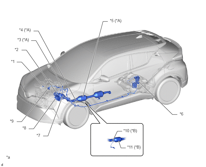
8NR-FTS EMISSION CONTROL EMISSION CONTROL SYSTEM GENERAL PARTS LOCATION
2WD Models
1.5,4.75 1.667,4.75
1.667,4.75 2.167,3.385
true
1,4.5 1.167,4.5
1.167,4.5 1.927,3.448
true
0.583,4.25 0.75,4.25
0.75,4.25 1.667,3.094
true
0.583,2.167 0.75,2.167
0.75,2.167 1.5,3
true
0.75,1.75 0.917,1.75
0.917,1.75 1.969,3.25
true
1.083,1.417 1.25,1.417
1.25,1.417 2.167,3
true
1.167,1.083 1.333,1.083
1.333,1.083 2.635,3.5
true
3.75,0.75 3.583,0.75
3.583,0.75 2.885,3.375
true
4.25,4.583 4.083,4.583
4.083,4.583 3.927,4.906
true
4.375,5.167 4.208,5.167
4.208,5.167 4.125,4.917
true
6.167,4 6,4
6,4 4.813,2.833
true
0.385,2.063 0.698,2.219
0.313,0.156
10
false
*1
0.51,1.646 0.823,1.802
0.313,0.156
10
false
*2
0.604,1.302 1.083,1.458
0.479,0.156
10
false
*3 (*A)
0.667,0.958 1.146,1.125
0.479,0.167
10
false
*4 (*A)
3.823,0.635 4.302,0.802
0.479,0.167
10
false
*5 (*A)
6.25,3.896 6.563,4.052
0.313,0.156
10
false
*6
1.271,4.646 1.583,4.802
0.313,0.156
10
false
*7
0.781,4.385 1.094,4.542
0.313,0.156
10
false
*8
0.344,4.146 0.656,4.302
0.313,0.156
10
false
*9
4.292,4.479 4.844,4.646
0.552,0.167
10
false
*10 (*B)
4.427,5.052 4.979,5.208
0.552,0.156
10
false
*11 (*B)
0.219,5.406 0.531,5.563
0.313,0.156
10
false
*a
| *A | Models with GPF | *B | Models without GPF |
| *1 | No. 1 Turbo Pressure Sensor | *2 | Air Fuel Ratio Sensor (Bank 1, Sensor 1) |
| *3 | Differential Pressure Sensor | *4 | No. 2 Air Fuel Ratio Sensor (Bank 1, Sensor 2) |
| *5 | Front Exhaust Pipe Assembly
·
GPF |
*6 | Fuel Suction Tube with Pump and Gauge Assembly
·
Charcoal Canister |
| *7 | Exhaust Manifold Converter Sub-assembly
·
TWC |
*8 | ECM |
| *9 | Purge VSV (No. 1 Vacuum Switching Valve Assembly) | *10 | Oxygen Sensor (Bank 1, Sensor 2) |
| *11 | Front Exhaust Pipe Assembly
·
TWC |
- | - |
| *a | The illustrations shown are examples only. | - | - |
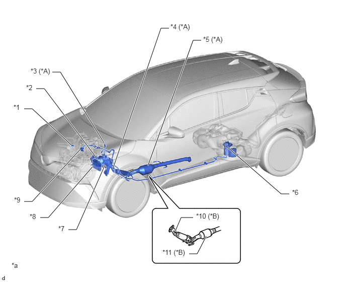
AWD Models
0.5,2.25 0.667,2.25
0.667,2.25 1.479,3
true
0.75,1.833 0.917,1.833
0.917,1.833 1.979,3.24
true
1.083,1.49 1.25,1.49
1.25,1.49 2.156,2.958
true
0.5,4.167 0.667,4.167
0.667,4.167 1.667,3.083
true
0.833,4.5 1,4.5
1,4.5 1.917,3.448
true
1.417,4.75 1.583,4.75
1.583,4.75 2.177,3.406
true
3.063,3.427 4,0.833
4,0.833 4.167,0.833
true
2.344,3.469 3.333,0.583
3.333,0.583 3.5,0.583
true
5.99,4.01 5.823,4.01
5.823,4.01 4.708,3.042
true
4,4.5 3.75,4.5
3.75,4.5 3.625,4.792
true
4.271,4.885 4.083,5.25
4.083,5.25 3.917,5.25
true
0.281,2.135 0.594,2.292
0.313,0.156
10
false
*1
0.542,1.729 0.854,1.885
0.313,0.156
10
false
*2
0.635,1.385 1.198,1.542
0.563,0.156
10
false
*3 (*A)
3.531,0.469 4.01,0.635
0.479,0.167
10
false
*4 (*A)
4.208,0.729 4.688,0.885
0.479,0.156
10
false
*5 (*A)
6.052,3.896 6.365,4.052
0.313,0.156
10
false
*6
1.208,4.646 1.521,4.802
0.313,0.156
10
false
*7
0.615,4.396 0.927,4.552
0.313,0.156
10
false
*8
0.292,4.052 0.604,4.208
0.313,0.156
10
false
*9
3.365,5.135 3.948,5.375
0.583,0.24
10
false
*11 (*B)
0.24,5.406 0.552,5.563
0.313,0.156
10
false
*a
4.063,4.385 4.646,4.625
0.583,0.24
10
false
*10 (*B)
| *A | Models with GPF | *B | Models without GPF |
| *1 | No. 1 Turbo Pressure Sensor | *2 | Air Fuel Ratio Sensor (Bank 1, Sensor 1) |
| *3 | Differential Pressure Sensor | *4 | No. 2 Air Fuel Ratio Sensor (Bank 1, Sensor 2) |
| *5 | Center No. 2 Exhaust Pipe Assembly
·
GPF |
*6 | Fuel Suction Tube with Pump and Gauge Assembly
·
Charcoal Canister |
| *7 | Exhaust Manifold Converter Sub-assembly
·
TWC |
*8 | ECM |
| *9 | Purge VSV (No. 1 Vacuum Switching Valve Assembly) | *10 | Oxygen Sensor (Bank 1, Sensor 2) |
| *11 | Center No. 2 Exhaust Pipe Assembly
·
TWC |
- | - |
| *a | The illustrations shown are examples only. | - | - |